RGB Laser Projector
When I was a kid I used to go to a local swimming pool that presented daily laser shows. The combination of 3D effects and laser graphics really impressed me at the time.
The equipment was old-school: a large laser bank was used as a main projector. Additional effects were created using fibre coupled auxilary projectors.
This was quite an impressive set up at the time.
A few years later the swimming pool was unfortunately closed, but I still remembered the nice laser show they used to present. I now wanted
to build my own laser projector. Unfortunately laser technology was still bulky, very expensive and certainly out of reach for a teenaged kid.
I tried anyway and built the usual lissajous, speaker and HDD-based systems using laser modules harvested from cheap laser pointers. Of course these attempts never
came close to the show I previously saw.
 Completed Laser Projector
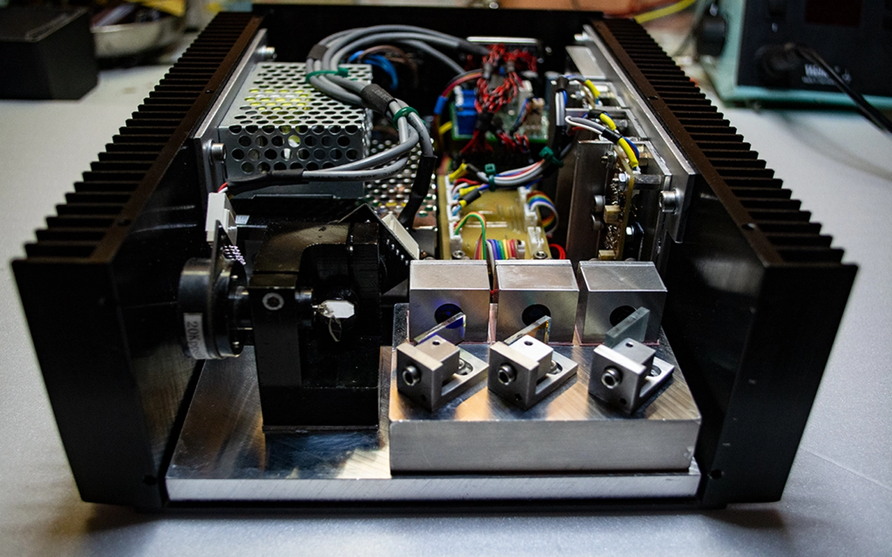 Projector components
A decade later, laser technology has advanced a lot. Laser projectors are now affordable and compact.
I decided to complete my childhood project and finally build a RGB laser system. The projector is intended to occasionally watch a laser shows in a small room.
It should be compact and low powered, so it is easy to store and can be set up quickly without having to worry too much about laser safety.
Scanning System
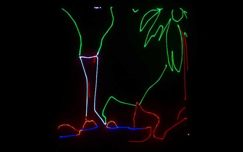
Laser graphics projectors utilize the principle of persistence of vision to create visual effects. A laser beam is scanned quickly across the projection area. Because the human eye is rather slow, the
moving beam is percieved as a still vector frame. Multiple frames are then combined to create animations. The beam is usually steered using a mechanical deflection assembly.
Two mirrors are arranged orthogonally to each other. Each mirror is mounted on a galvanometer shaft. The galvanometers are closed loop servo controlled to allow precise movement.
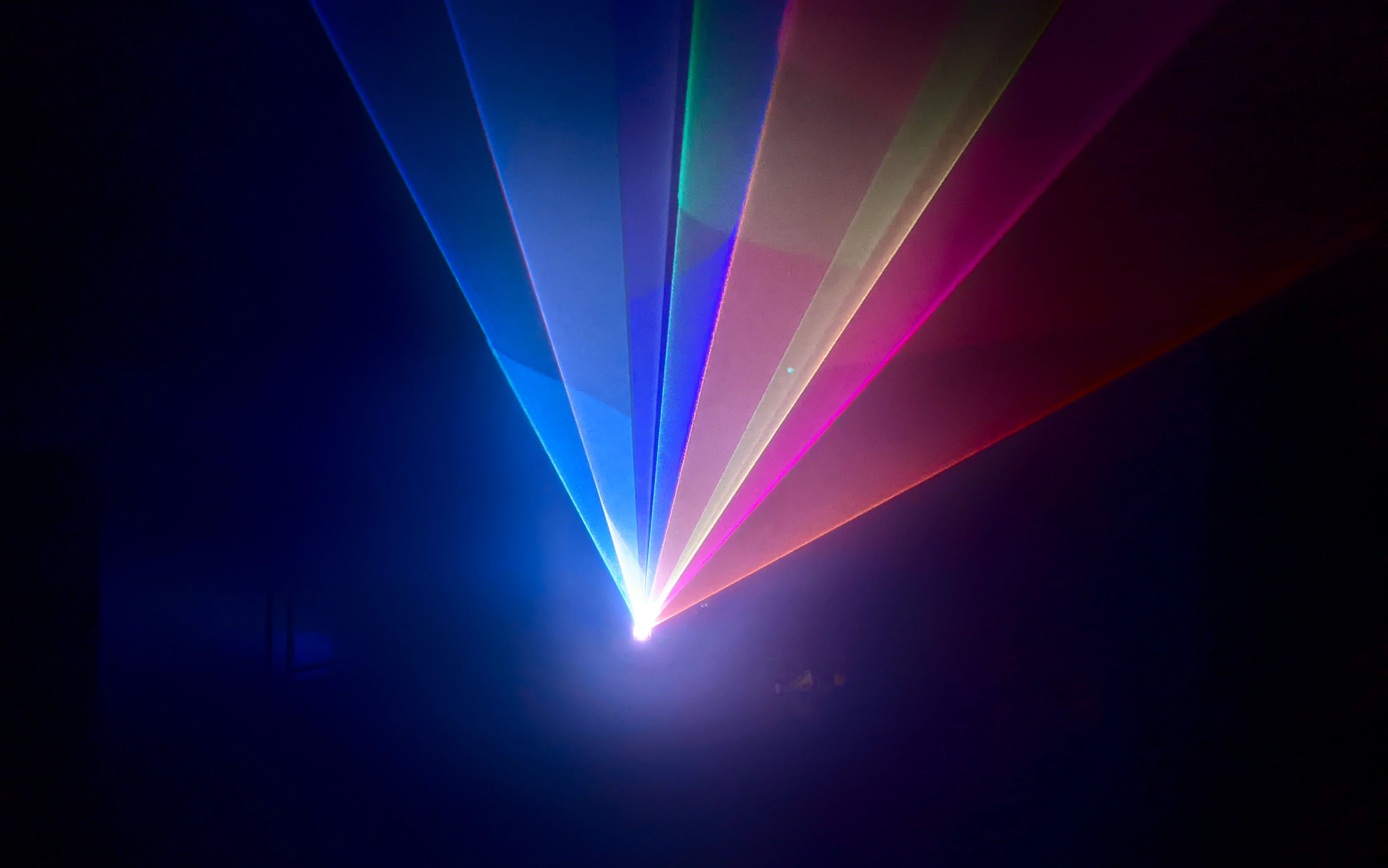
Different colors are additively mixed by overlaying red, green and blue laser light. The lasers are modulated at high speed to draw separate line segments.
Many modern projectors also allow analog modulation of the lasers to mix intermediate colors.
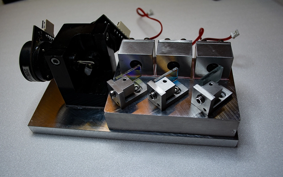
Optics assembly
I chose three diode laser emitters for this project. The total white light emission power of the system is roughly 200mW. This is a rather low output power by today's standards.
Choosing low power laser sources allows the use of single mode emitters. Single mode laser sources feature a very small area of emission, resulting in low beam divergence when focused.
The output power is not high enough for large rooms or even outdoor use, but good for small in-door demonstrations. The risk of eye injury is also reduced considerably when compared to a high power laser system.
All optical components were mounted to a 20mm machined aluminium plate to prevent mechanical distortion and conduct heat away from the laser sources.
The laser diodes were press fit in aluminium blocks to provide good heat conduction. Because the diode housings are at positive potential, the mounting blocks were individually isolated from the base using silicone pads. Collimation is archieved
with 3-element glass lens assemblies. Each lens assembly can be adjusted using M9 fine thread to allow proper positioning to the laser emitter. A small PCB was added to each laser diode to prevent mechanical stress from soldering wires to the diode terminals.
Each pcb also features a resistor to limit voltage buildup during a static event. I decided against using capacitors for ESD protection to simplify driver design. A schottky diode is used to provide reverse polarity protection.
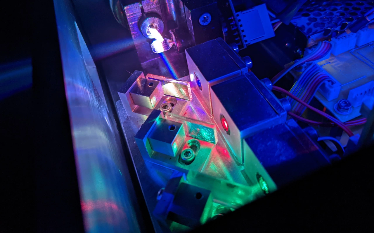
The laser beams are overlayed using dichroic mirrors. 3-DoF ajustable mirror mounts were fabricated from aluminium stock.
The assembly has to be carefully adjusted to overlay the individual laser beams. Running the lasers at reduced brightness, aligning the translational degree of freedom is easily archieved "by eye". To adjust the two remaining rotational axes, rough alighment is again done "by eye".
Fine tuning is then completed by using a lever tool. The rotational axes have to be tuned carefully since aligment errors will quickly result in beam separation.
A cheap galvanometer assembly was chosen for the project. The assembly arrived with scanners, mounting block and drivers included.
The scanners and laser assembly were both mounted to a piece of 5mm machined aluminium plate. Distortion between the scanners and the laser assembly is less critical, since color aligntment is not affected.
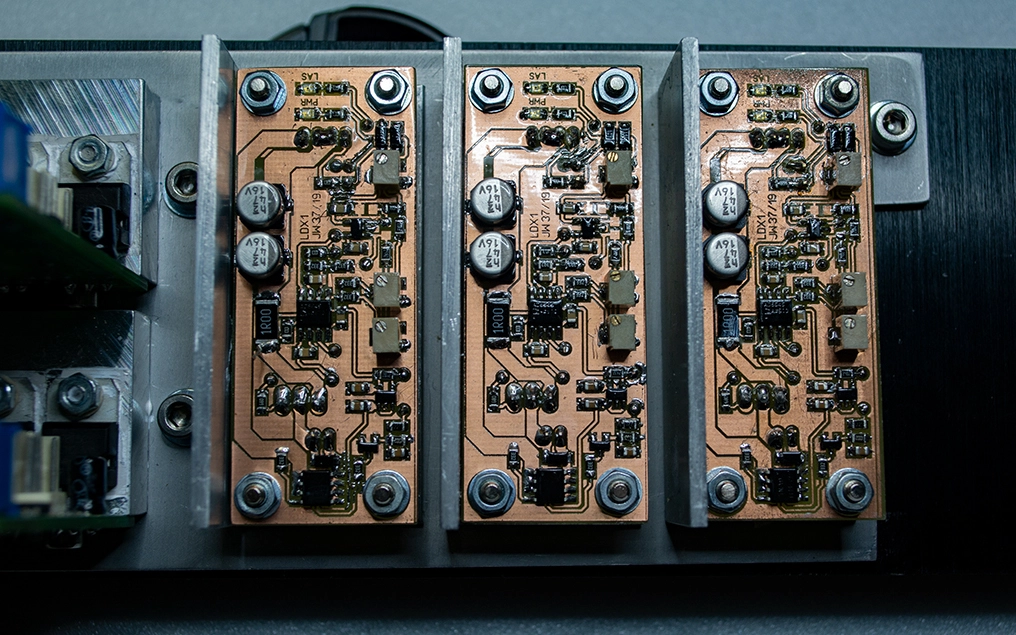
Laser Diode Drivers
As previously hinted, the power of the laser diodes has to be changed quickly to draw individual line segments.
Laser diodes should, similar to common LEDs, be current mode controlled. Unlike LEDs they are much more susceptible to electrostatic discharge and thermal damage. Current overshoot,
including transients during power up should be avoided, as they can quickly overheat the diode assembly.
On the other hand the driver circuit should provide sufficient bandwidth to draw crisp edges and single beams.
I chose a classic P-D control scheme for my drivers. Steady-state error is not critical and using a high proportional gain generally low. An integrating component is not required.
The control loop was adjusted to critically dampen a step response input. The driver archieves roughly 65kHz -3dB bandwidth. This is much faster than required. The controller was implemented
using operational amplifiers.
The low current consumption of the chosen diodes allows the use of a linear control element. A N-channel MOSFET is connected in series with the laser diode.
Current to voltage conversion for the feedback path is archieved using a series shunt resistor.
At very low currents, the relationship between laser emission and forward current is highly non-linear. A simple solution is to offset the command input by a fixed value.
The offset is adjusted to meet the diode's lasing threshold. Because most laser diodes emit a faint glow when operated at this current, a comparator circuit was added to reduce laser forward current to
zero when no input signal is detected. This functionality is commonly referred to as "standby glow suppression". The individual drive current components are combined using a summing amplifier. A low gain derivative
control element was added to remove overshoot before entering the current control loop.
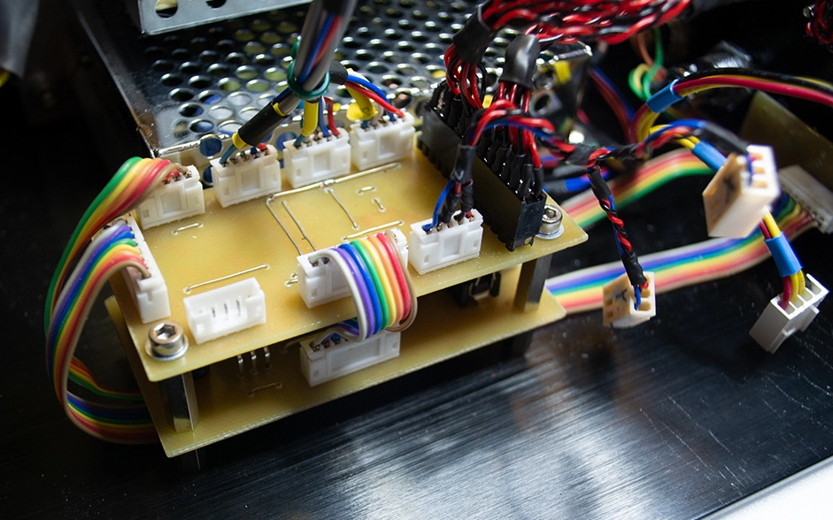
ILDA-Connector
The international laser display association ILDA defines a standardized control interface for laser projectors, the ILDA Standard Projector (ILDA ISP)
Position signals are 10V, color signals 5V differential. Additional safety signals are also present.
I designed a small interface board to handle the signals received from the ILDA interface and distribute them to different components in the projector.
Safety signals are handled by a AtMega328 microcontroller. The differential color signals are converted to single-ended using operational amplifiers. This was primarily done so the laser drivers would not require symmetric supply rails.
The supply rails for the differential to single ended converters are generated by a DC-DC converter module. A linear regulator is used to provide a 5V logic supply rail. A star grounding theme is employed to avoid ground potential
changes with varying power supply loads.
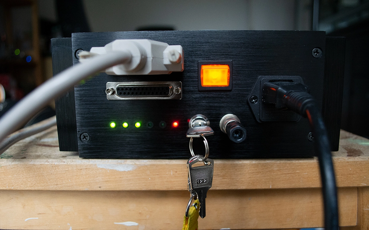 DB25 ILDA ISP connector
A series of green LEDs indicate various interface conditions. The control logic enables the laser drivers if all required safety conditions are met. A red LED indicates that
laser emission is enabled.
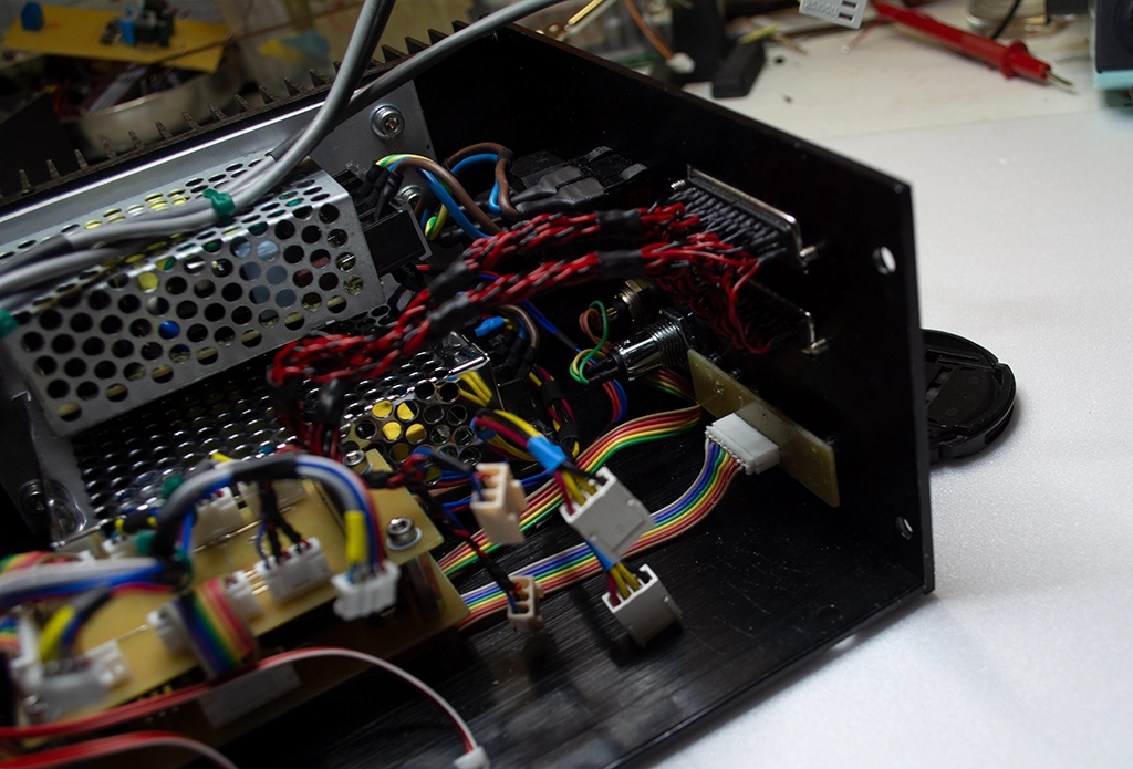
Odds & Ends
I used two switch mode power supplies to power the projector. A +-24V/1A PSU for the galvanometers was supplied with the scanner set. A 12V/3A SMPS powers the lasers and my interface board.
The projector was fitted with a key switch and an additional 9-pin connector for connecting an emergency stop button. I also routed the serial interface of the microcontroller to the connector
so I can access the bootloader without having to disassemble the projector.
 Power supply section
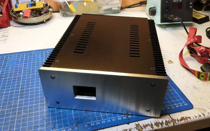
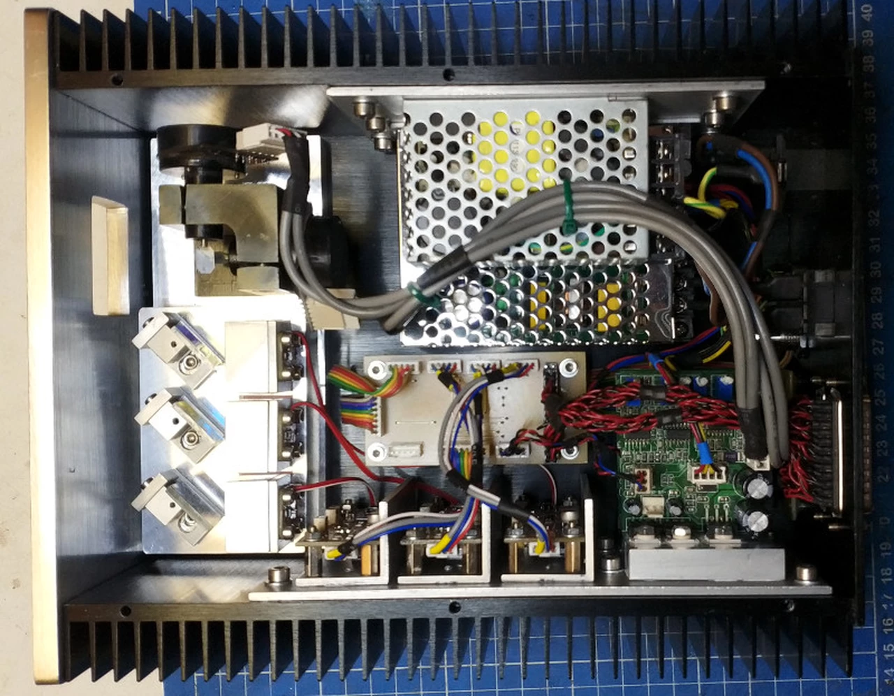 Projector assembly
The aperture was fitted with AR-coated glass.
 Completed Laser Projector
 Projector components