Scratch-Building Everything
I built this projector as a demonstration unit for my scratch-built scanners.
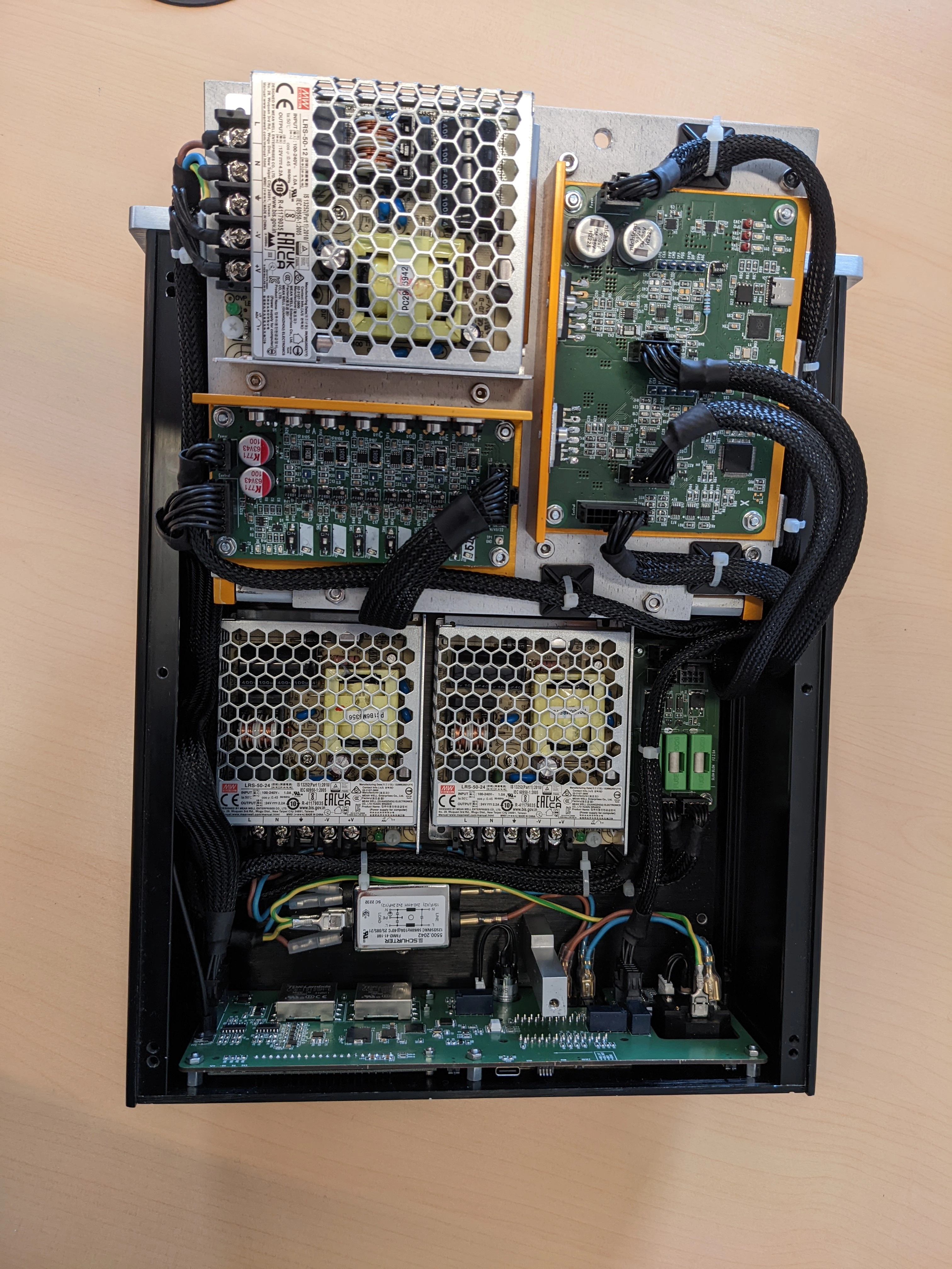
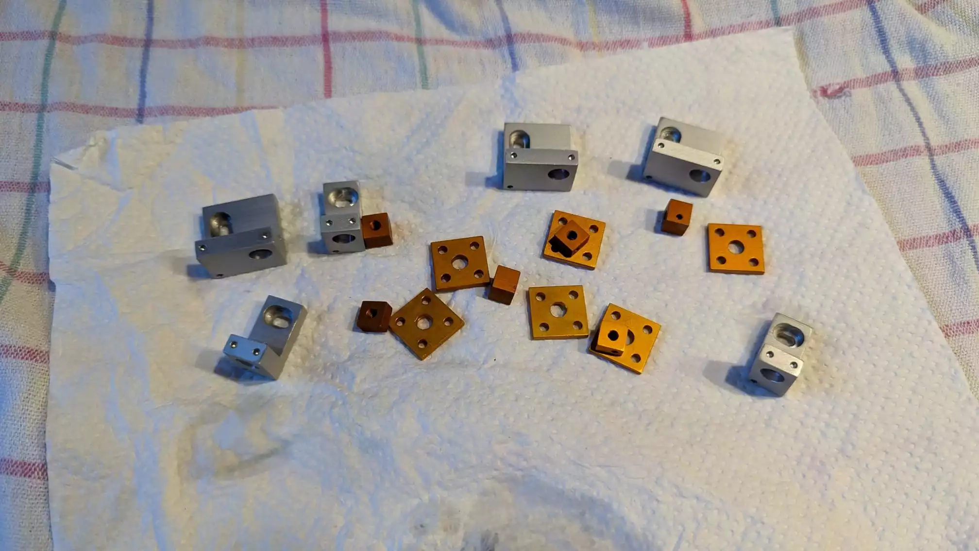
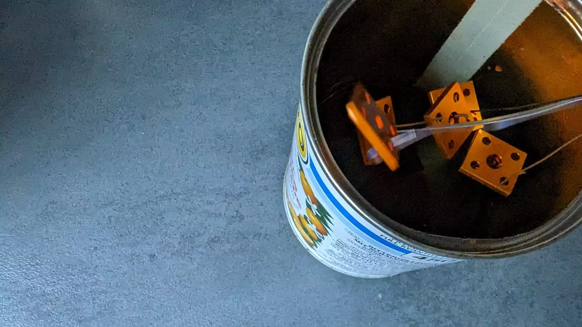
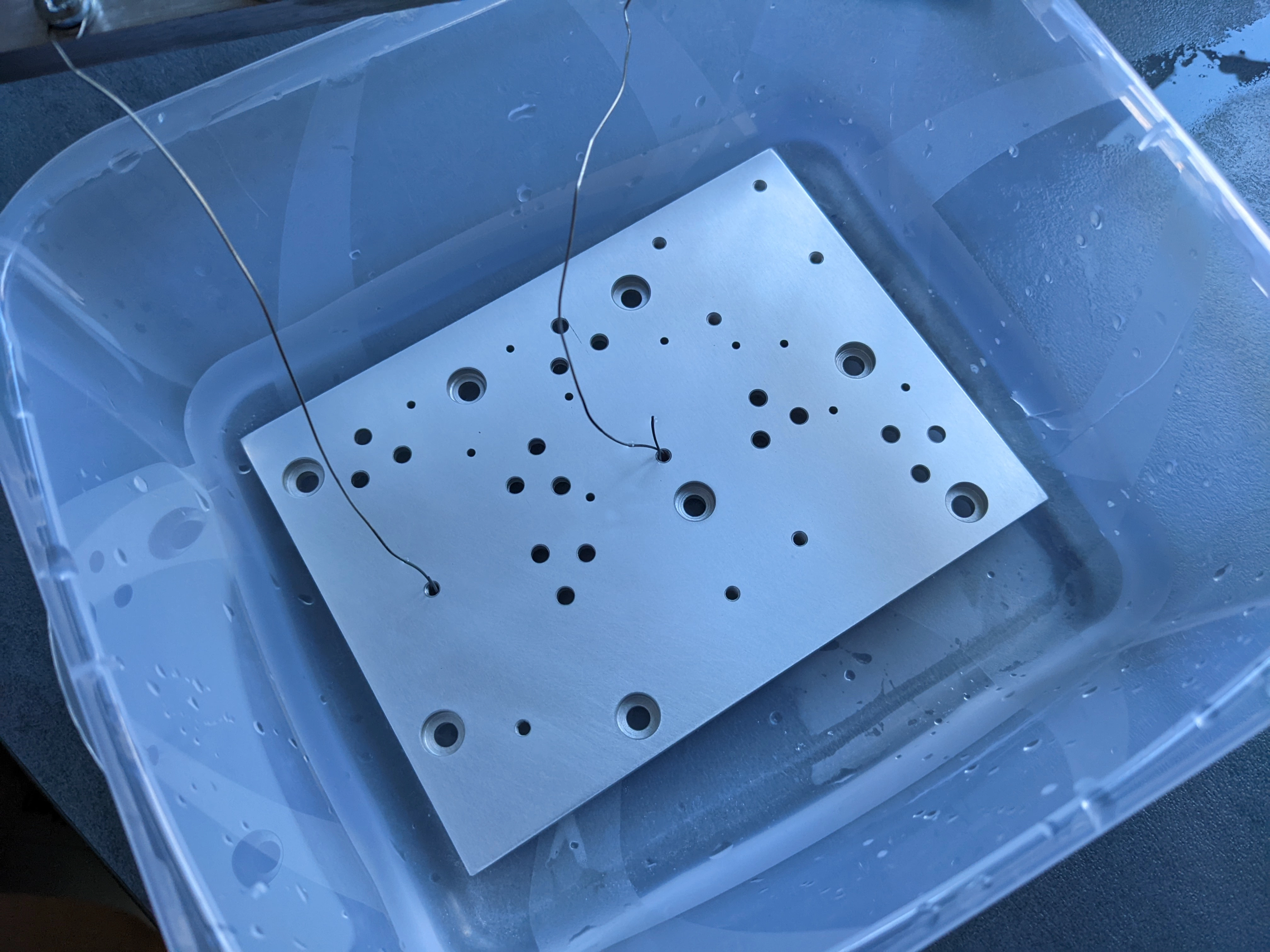
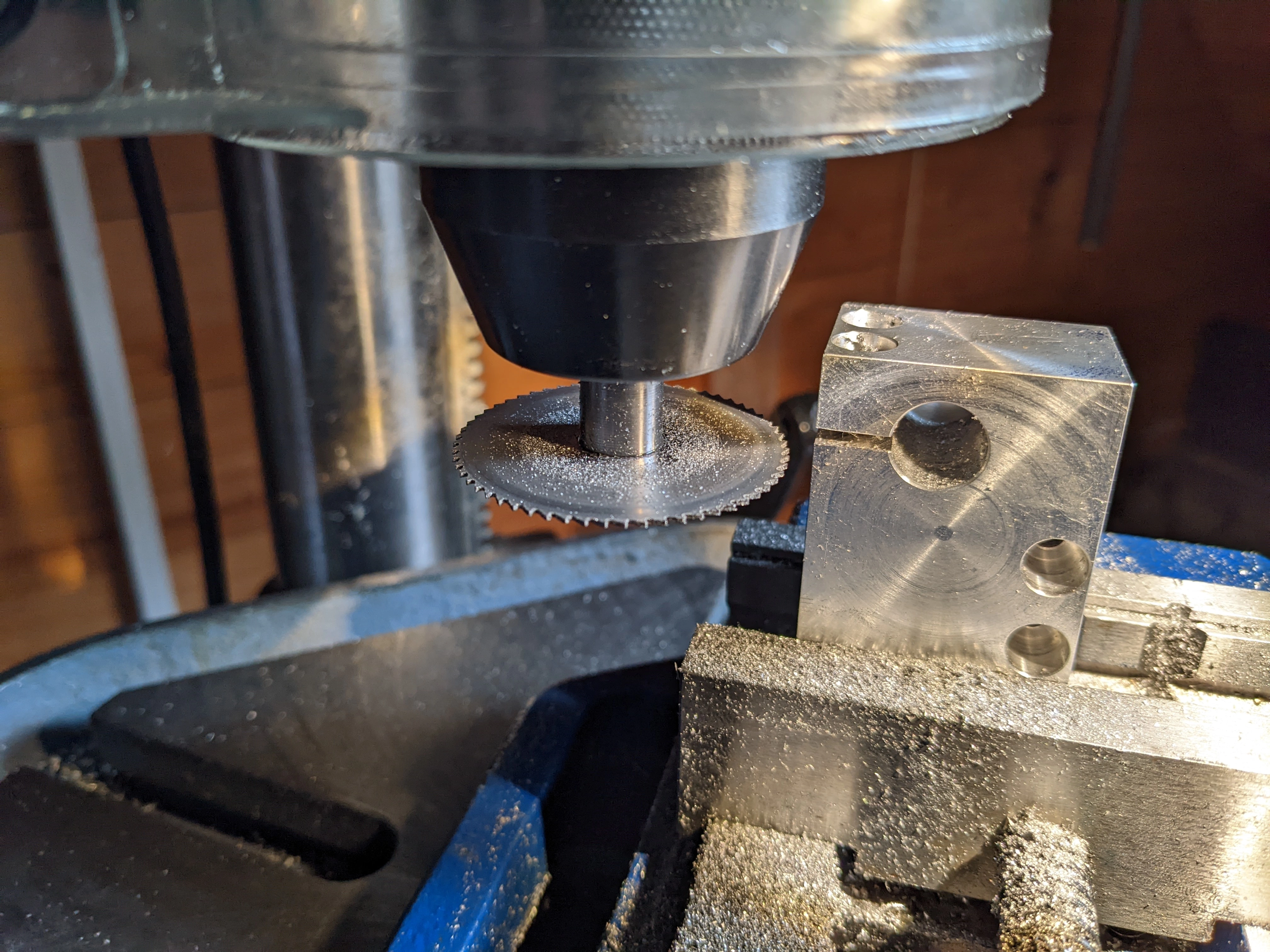
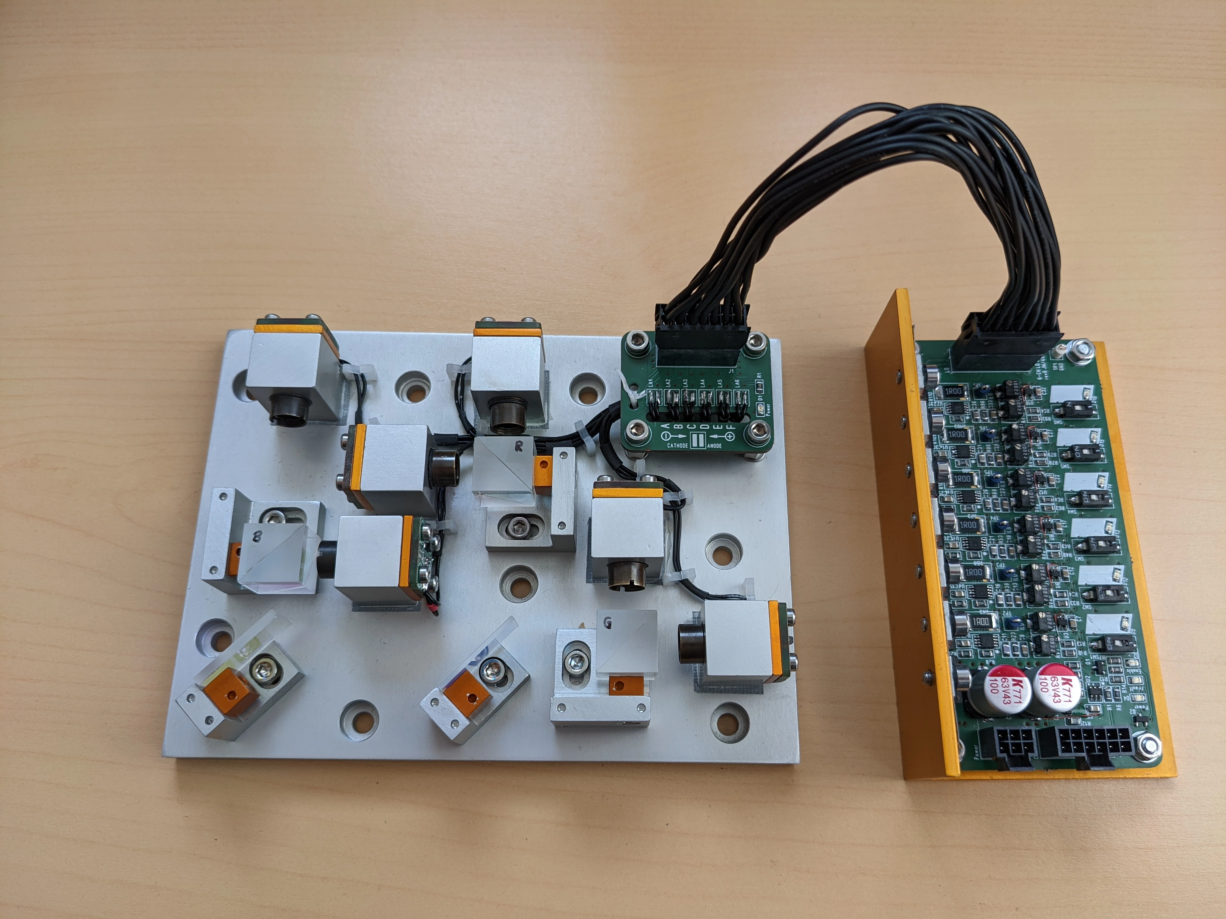
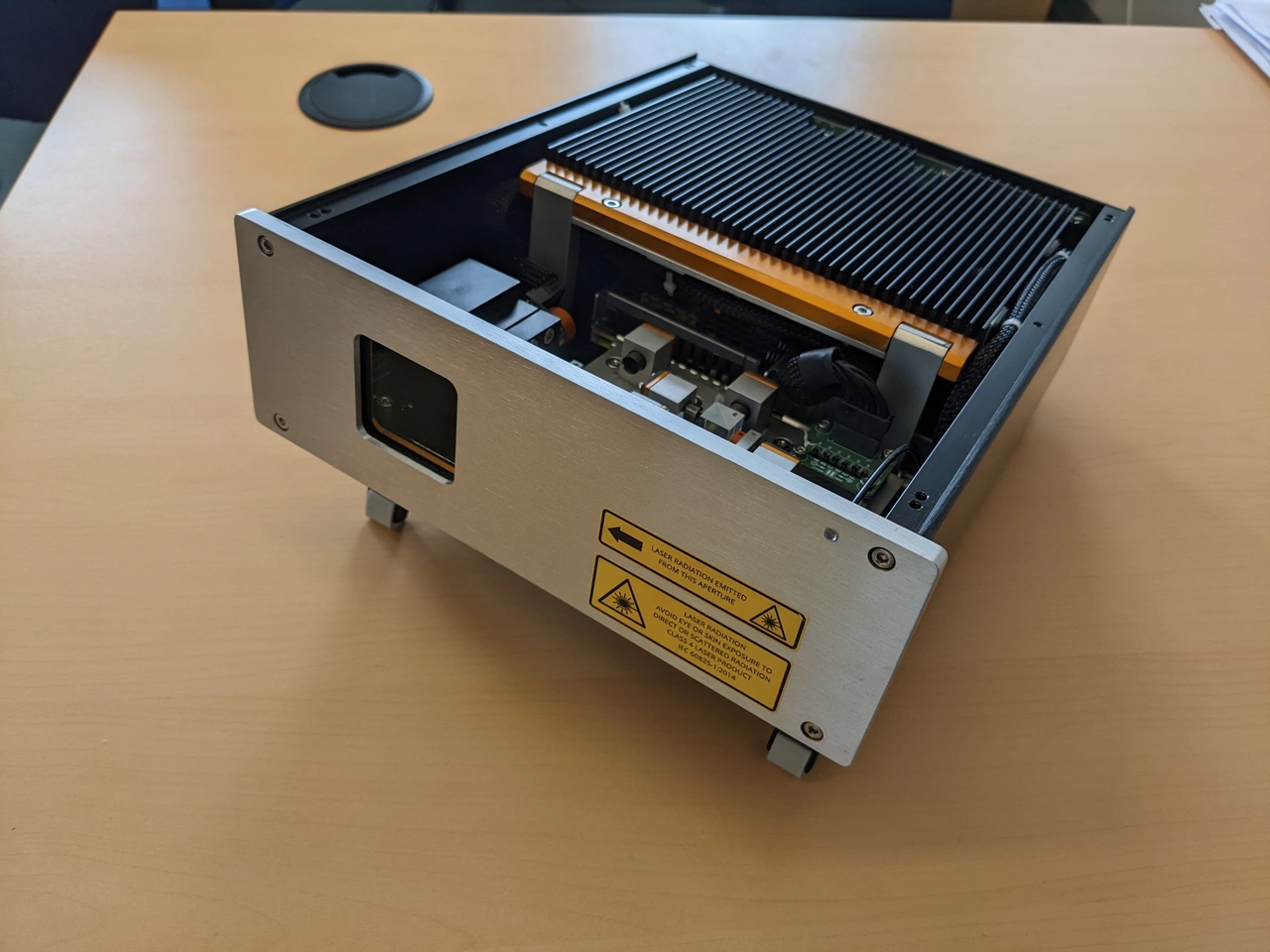
Following the theme, I designed and built nearly everything in this projector from scratch.
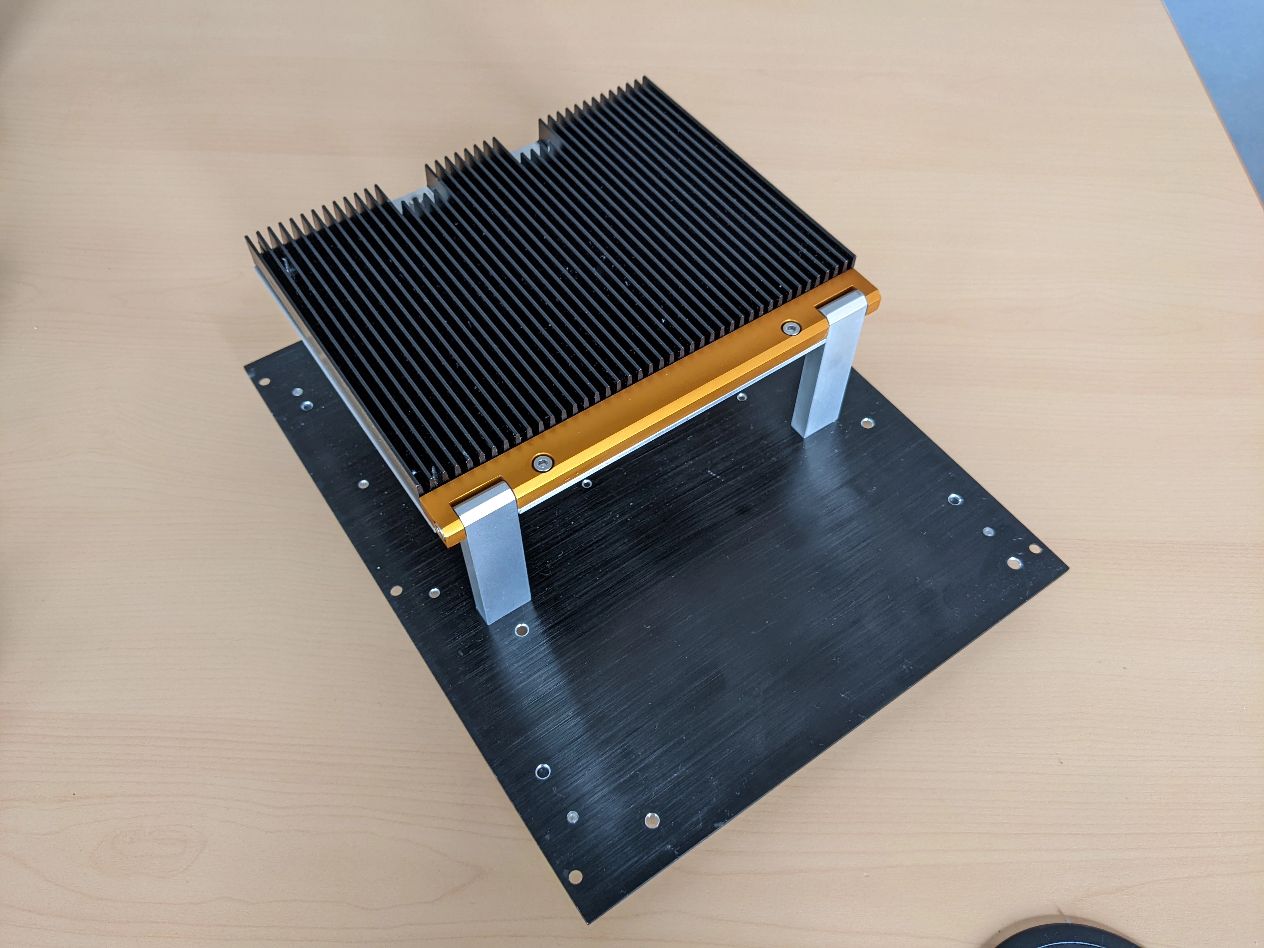
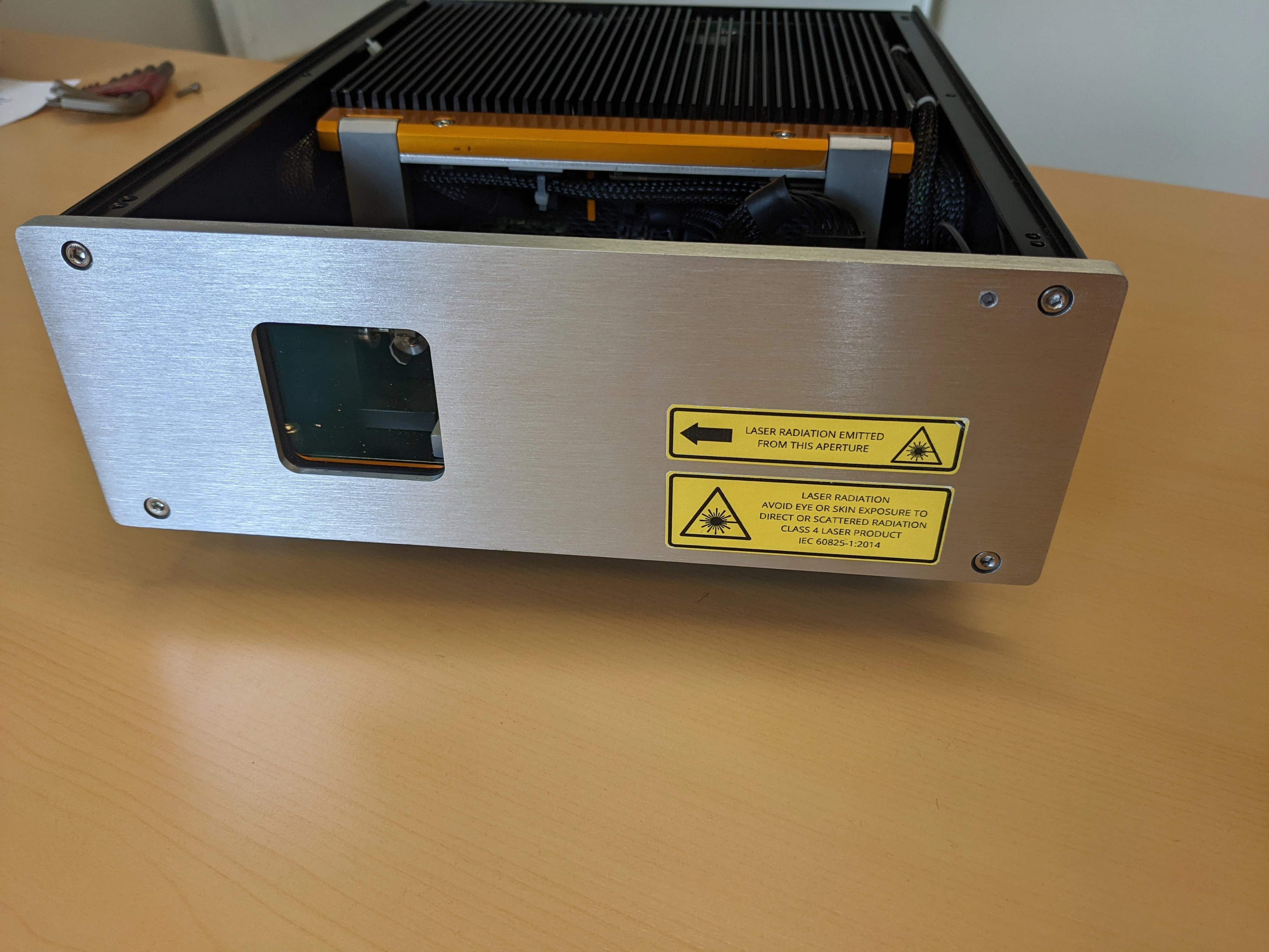
This includes the laser drivers, optics mounts, ILDA receiver circuitry and scanfail-safety.
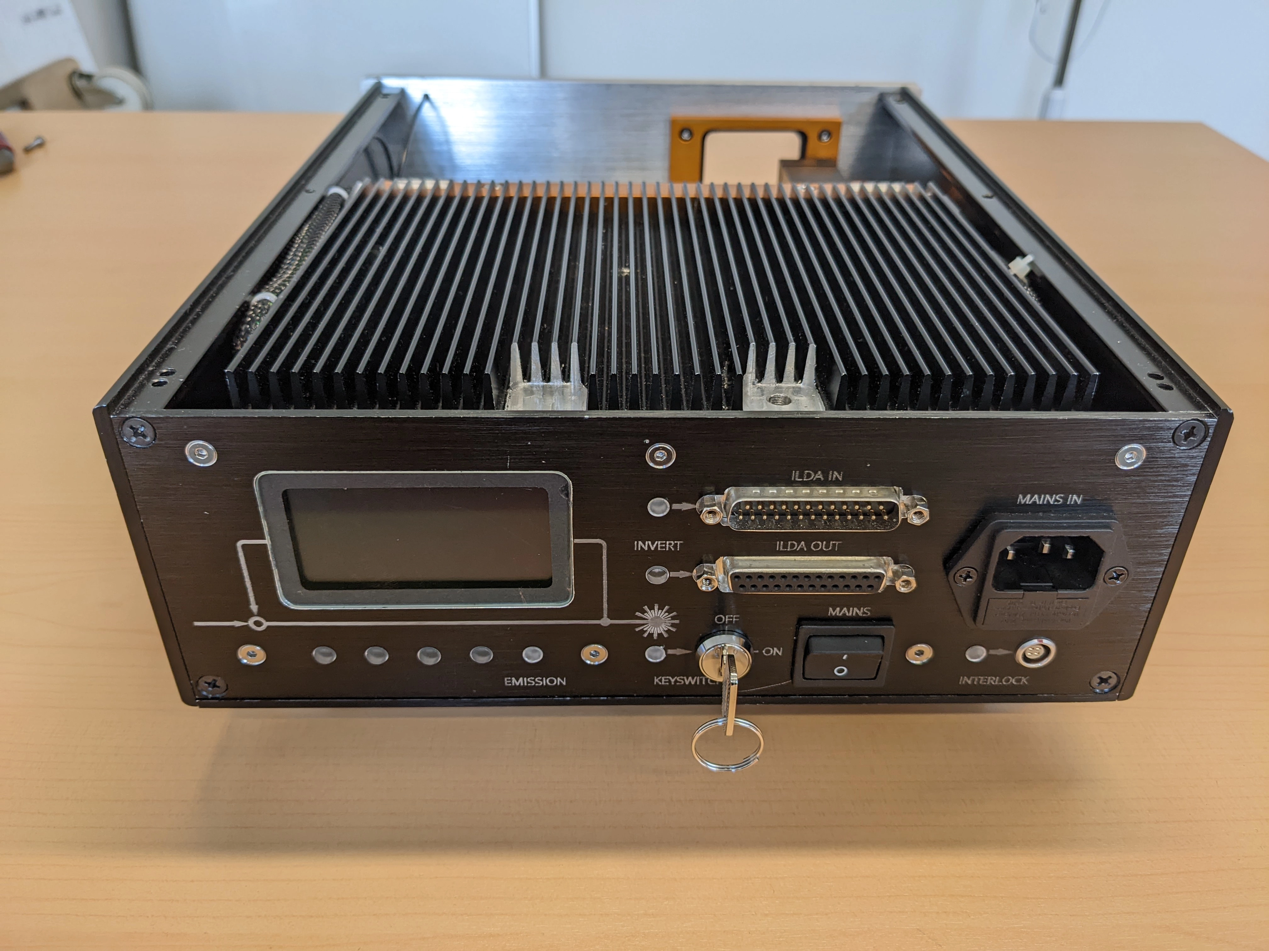
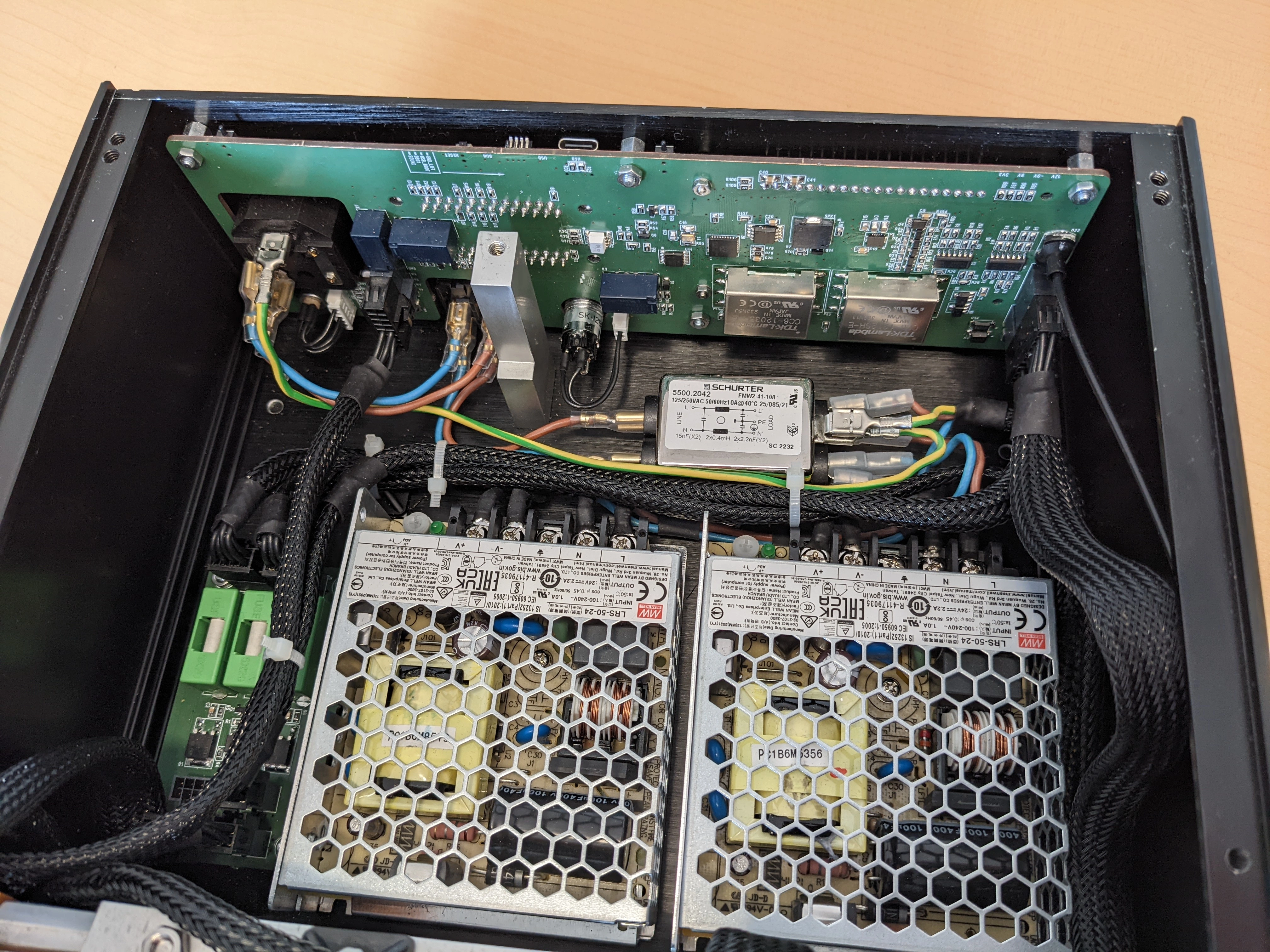
The projector enclosure was built to be easily accessible and visually interesting.
 Scratch-built Laser Projector
6-Channel Laser Diode Driver
I designed a compact 6-channel laser diode driver. Each channel can supply up to
2A continuous forward current. An offset current is added to each channel to linearize
emission output. The offset current is clamped to zero when the modulation signal drops
below 100mV to supress standby glow. Input voltage is monitored by an on-board power supply
watchdog. Laser emission is only enabled if the power supply has been in the valid voltage range.
Additional start delay was implemented to allow the circuitry to settle and reject power up transients.
When power is disconnected the lasers are safely steered into the off position before the control circuitry
is shut down. An electronic shutter input crowbars intermediate modulation levels and disconnects all laser
diodes through a redundant high-side switch. The shutter input is resistant against input stage
overload.
The driver archieves roughly 175kHz modulation bandwidth.
Each channel can be switched to CW operation using on-board DIP-switches.
A voltage output forward current signal is available through buffered test points.
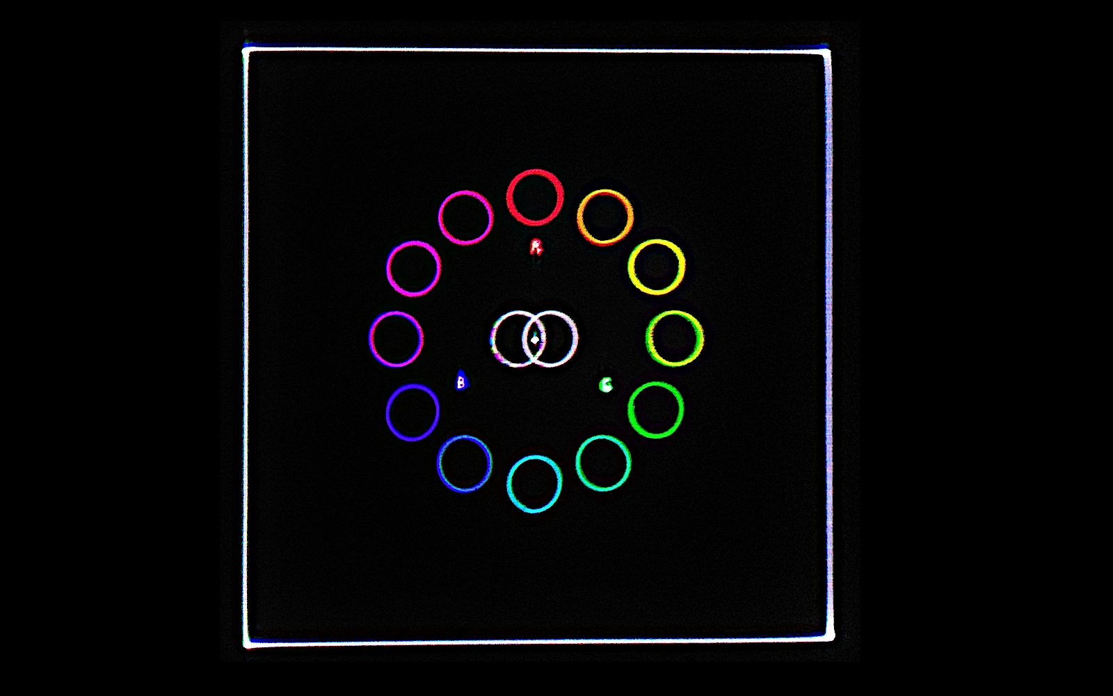
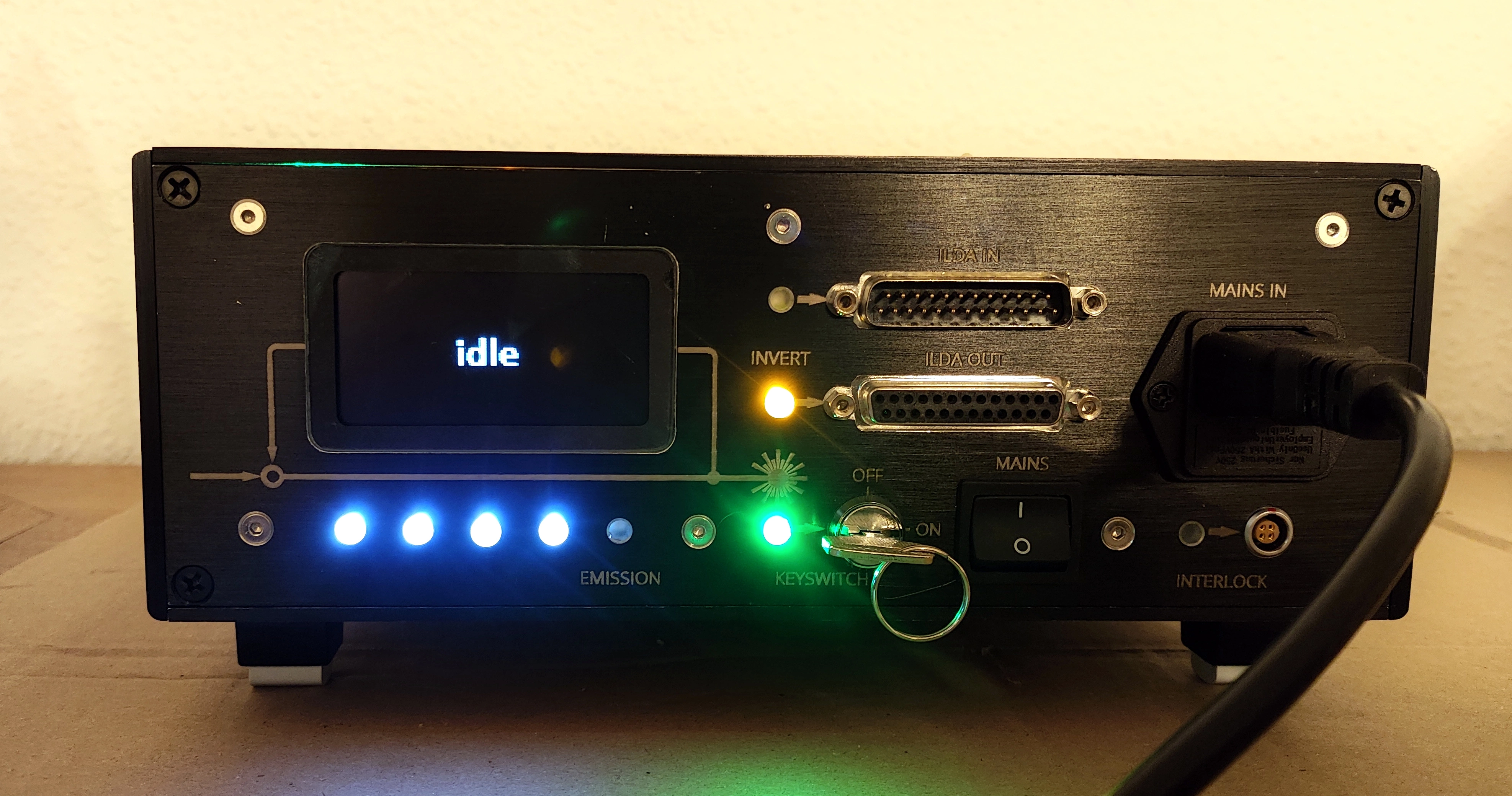
ILDA DB25 Receiver and Scanfail-Safety
I designed a large PCB for the projector backpane. It handles interfacing to the ILDA ISP DB25 connector.
Modulation signals from the projector controller are converted to single ended using differential receivers.
X/Y inputs are daisy-chained to an output connector and can be flipped along X/Y/XY using relay logic.
ILDA TTL is opto-isolated and can be ground-lifted. ILDA interlock, estop, emission indicators and redudant case interlock
switches and scanner monitoring were implemented for safety. I added backlit buttons and an OLED-Panel to make everything look pretty.
 Scratch-built Laser Projector