Jan's Tesla Coil Addiction
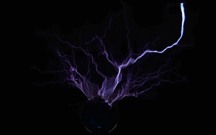
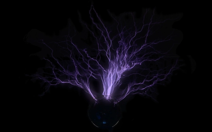
Tesla coils are among the more exciting physics demonstrations. The presented experiments generally feature wireless energy transfer or sparks of varying length.
Because the generated voltage alternates at a high frequency, sparks generally discharge into the air. This effect is often referred to as streamer discharge.
I have built many tesla coils over the years. This article will only describe some of my builds and focus on the historic spark gap controlled design.
 My first Tesla coil
 "High school project" coil
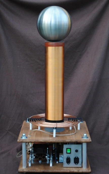
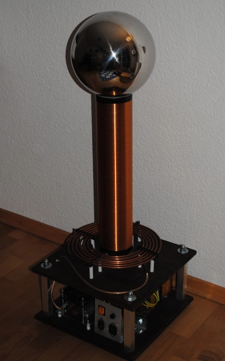
 1.5kW Tesla coil
I built the coil on the left in middle school. It used a blocking oscillator to
resonant drive a small mains transformer. This generated roughly 3kV at a few Kilohertz.
The transformer output was rectified to feed the classic spark gap tesla coil design.
Because the resonant circuits were not matched at all, this build could be more accurately described
as an impulse transformer. Still, I don't think this page would be complete without it.
The second coil was built as a demonstration unit for a high school project.
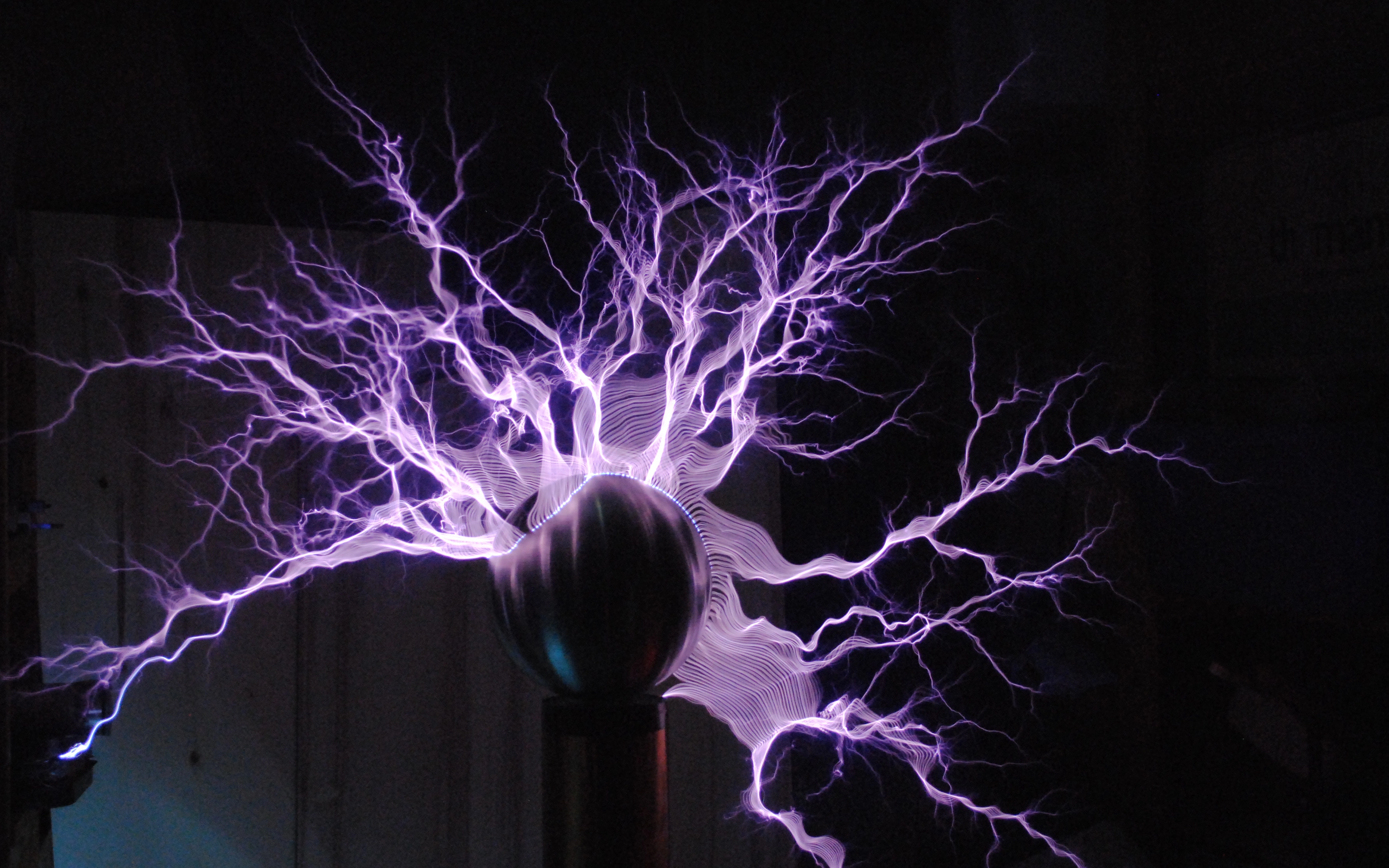
The third coil finally archieved more than 1 meter discharge length, statisfying me need for
sparks.
Resonant Circuits
A tesla coil system consists out of two loosely coupled resonant circuits. A relatively high capacitance and low inductance are used in the primary circuit. In contrast, the secondary circuit employs a low capacitance and high inductance.
The high secondary inductance is traditionally realized using a large air-core coil, which is the visually defining factor of a tesla coil. Exact frequency matching is required to
avoid destructive interference between the two circuits.
To get the primary circuit started, energy has to be injected into the circuit. This is generally archieved by charging the primary capacitor. When the voltage across the capacitor terminals is sufficently high,
a spark gap will break down. Due to air ionization, the resistance of the spark gap drops drastically and it starts to conduct. The primary LC-circuit is closed and starts to oscillate.
 Primary circuit
 Primary circuit
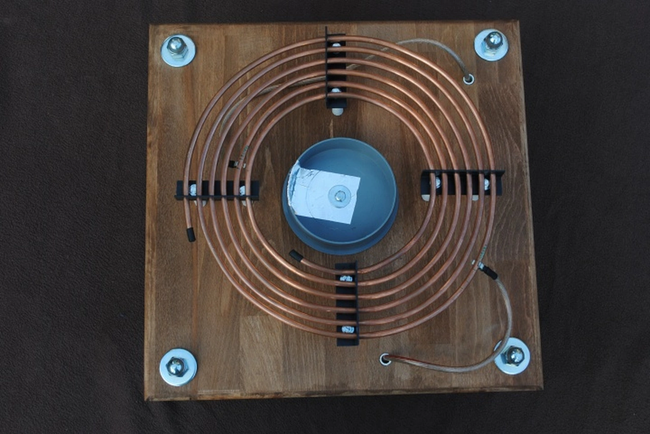
Primary coil
I have built most primary coils as flat spiral type coils. The coil is supported using four spacers. I used hvac cooper tubing as a conductor.
The inductance was calculated using one of Wheeler's formulas. Primary coil taps are adjustable for tuning the primary LC-circuits resonant frequency.
 Primary coil
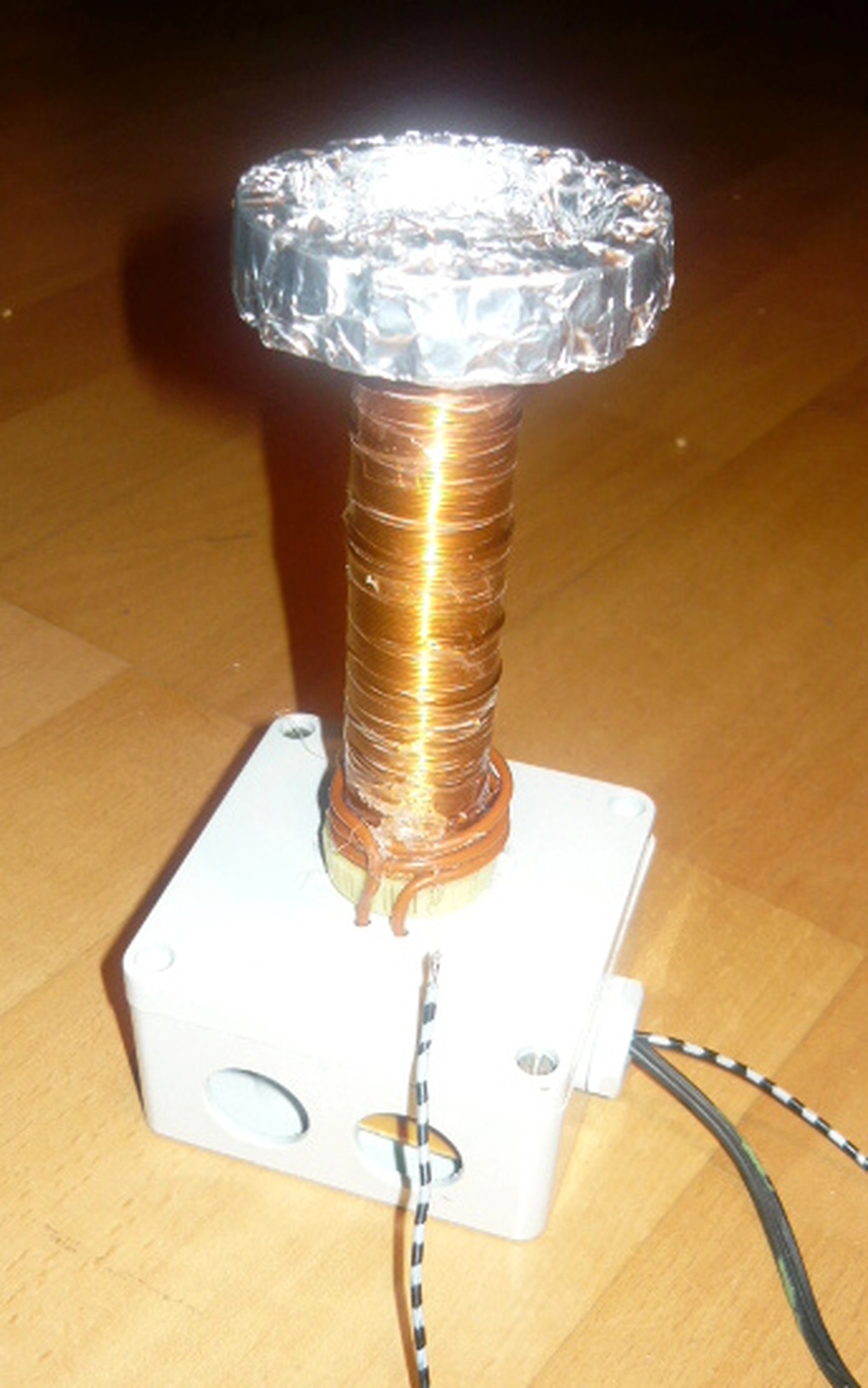
Secondary coil
Because the secondary capacitance is rather low, the parasitic capacitance of the coil has to be considered.
I used Medhurst's formula to estimate the capacitance.
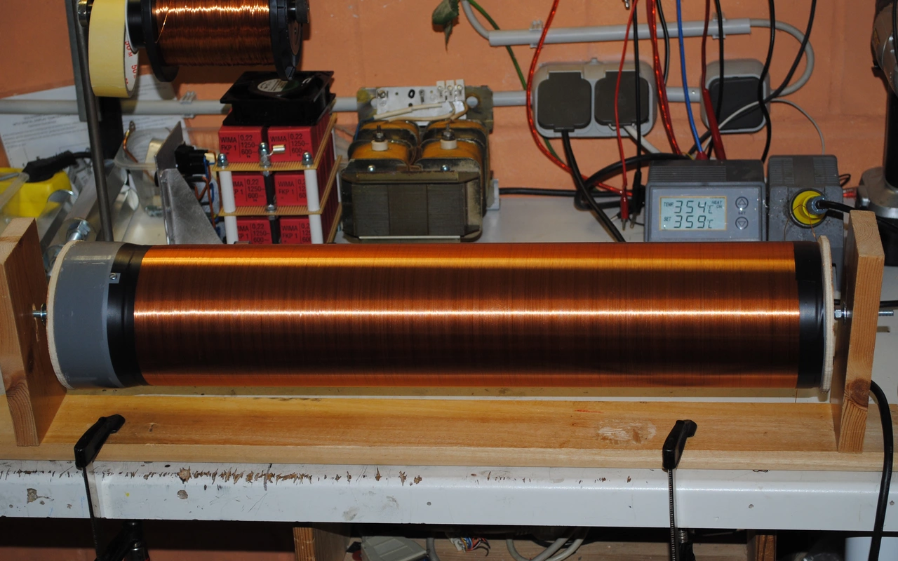 Secondary coil winding
Primary capacitor
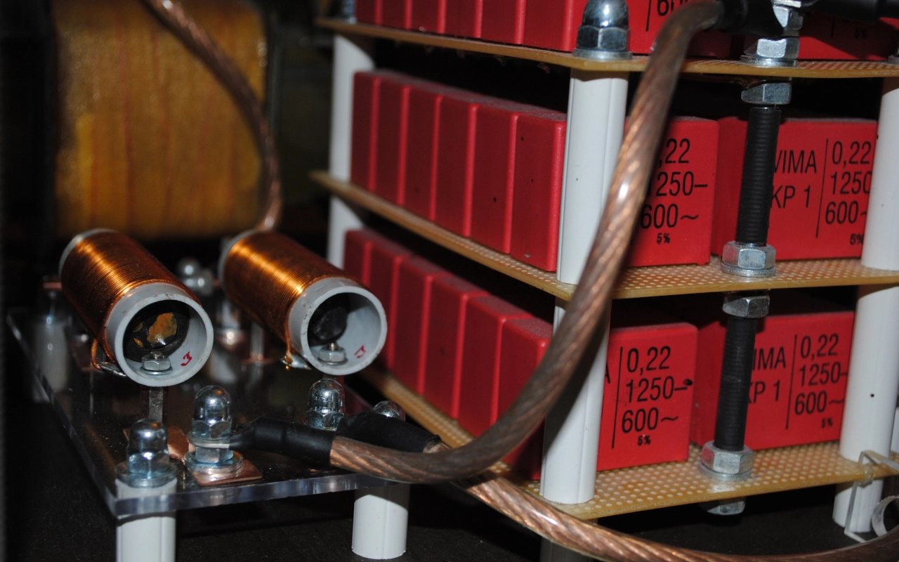
I have used Multi-Mini-Cap (MMC) designs in all my tesla coils. Multiple small capacitors are connected in series to archieve the required voltage rating.
Several of these capacitor strings are then connected in parallel to match the required capacitance. The capacitors have to either be rated for fast charging and discharging (= impulse loads)
or very significantly oversized. I have used FKP-1 pulse capacitors with a safety factor of roughly 1.8 for my tesla coils. Even high quality capacitors will blow up if not properly sized.
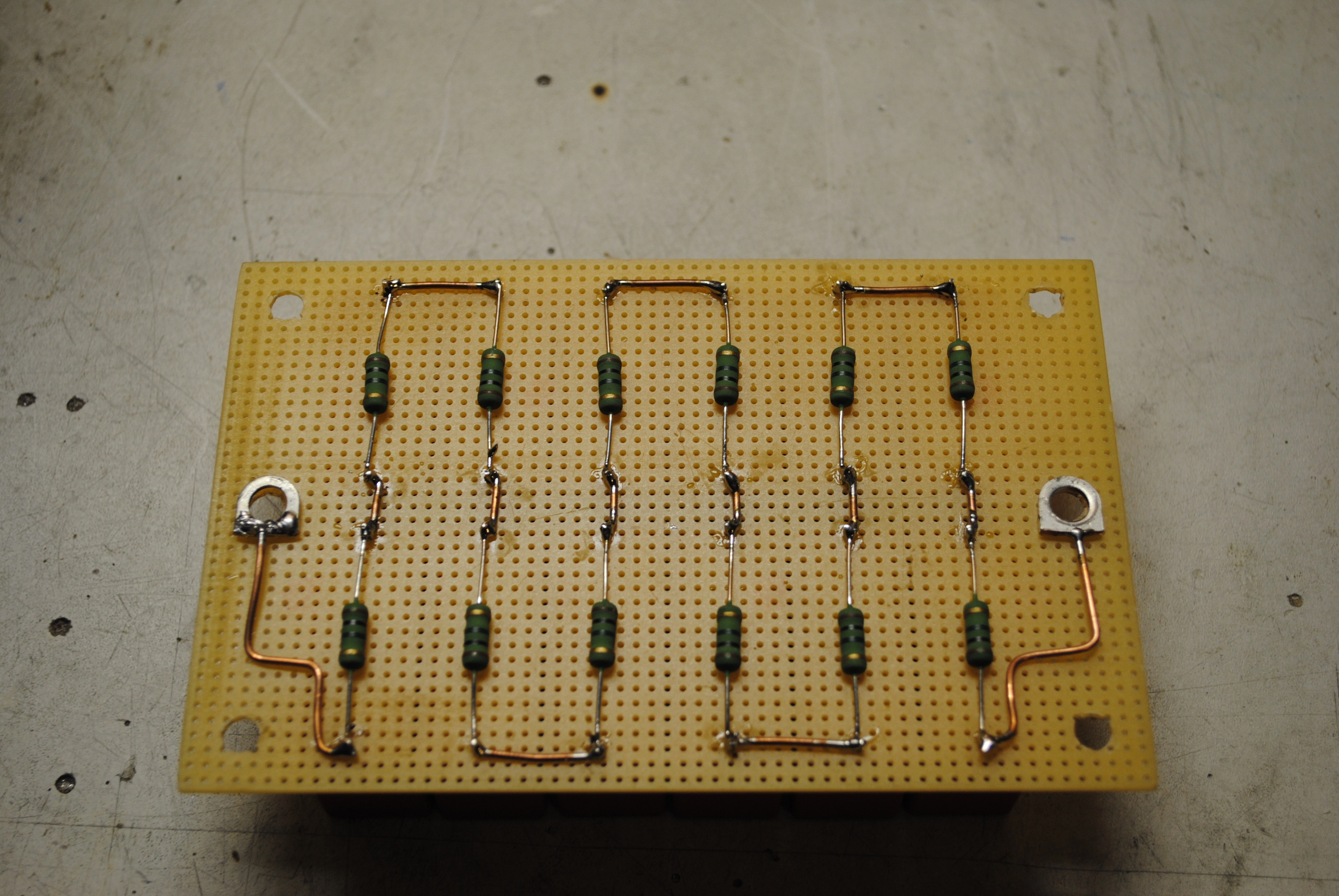
A parallel resistor is connected to each capacitor for evening out the voltage distribution across the string and discharge any remaining partial charge after operation.
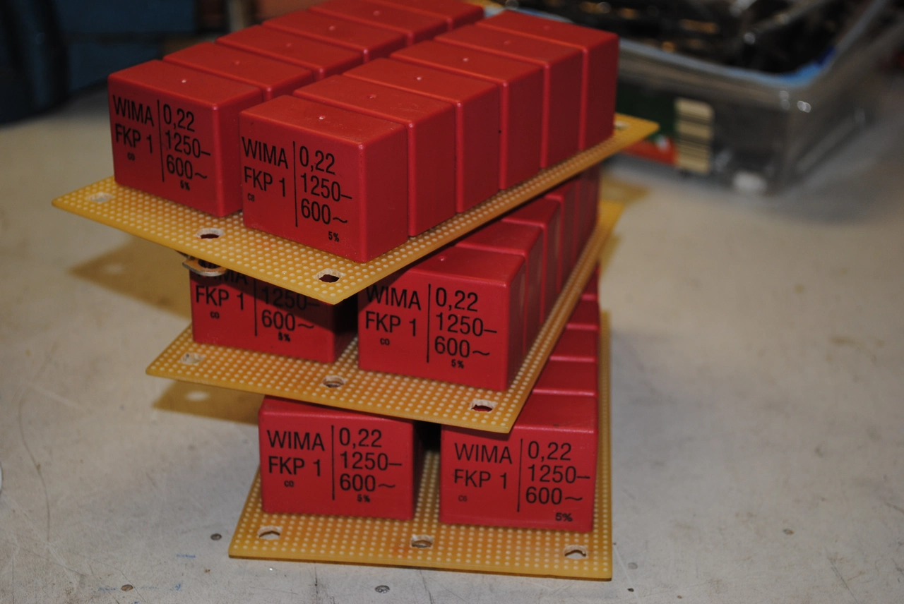 Multi-Mini-Cap (MMC) capacitor
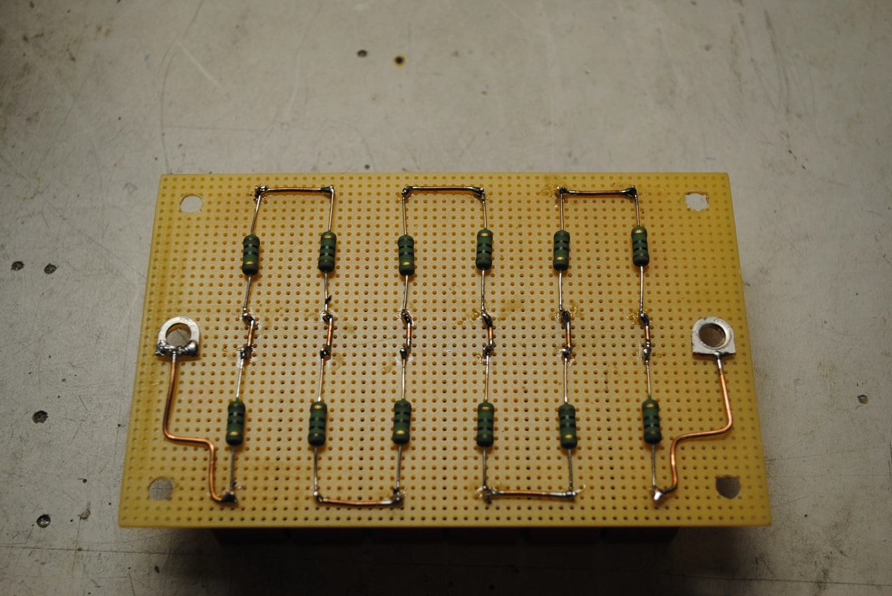 Balancing resistors
Spark gap
If the spark gap does not quench fast enough, energy is repeatedly transferred between primary and secondary circuit.
Directing air flow towards the spark gap removes ionized air and makes the spark gap quench a lot faster.
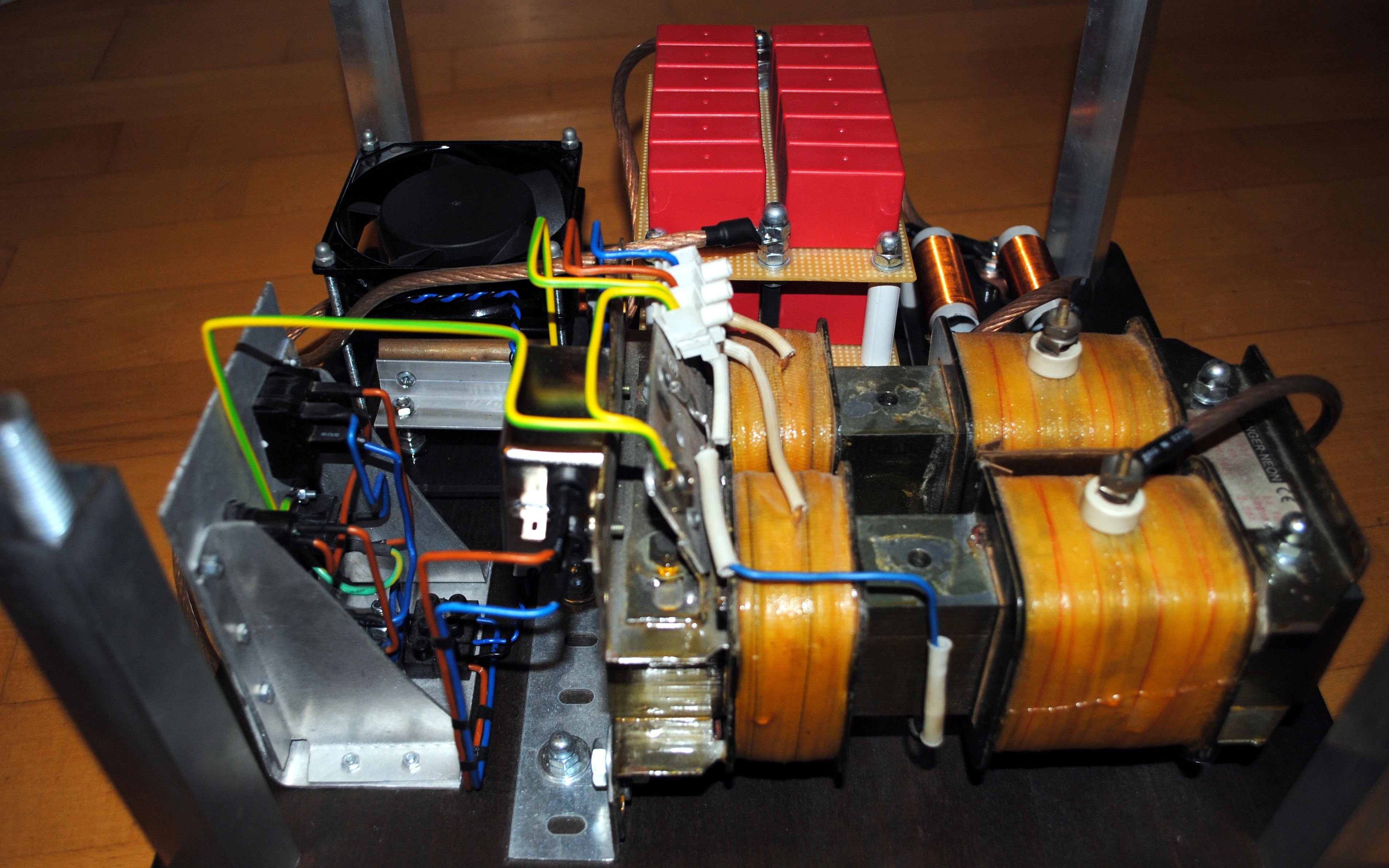
Primary feed transformer
A relatively high voltage has to be supplied to charge the capacitor. Typically spark gap tesla coil systems use a primary feed voltage betweem 5 and 10 Kilovolts.
Because the resonance frequency of the LC-cicruit is much higher than mains frequency, the capacitor can be connected directly to a mains transformer. This is nice, because building
a rectifier that can withstand 5+kV at a few 100 Milliamps would be expensive, large and annoying to construct. On the other hand we have to make sure that we can charge the capacitor fast enough,
so it will not be discharged when the polarity reverses.
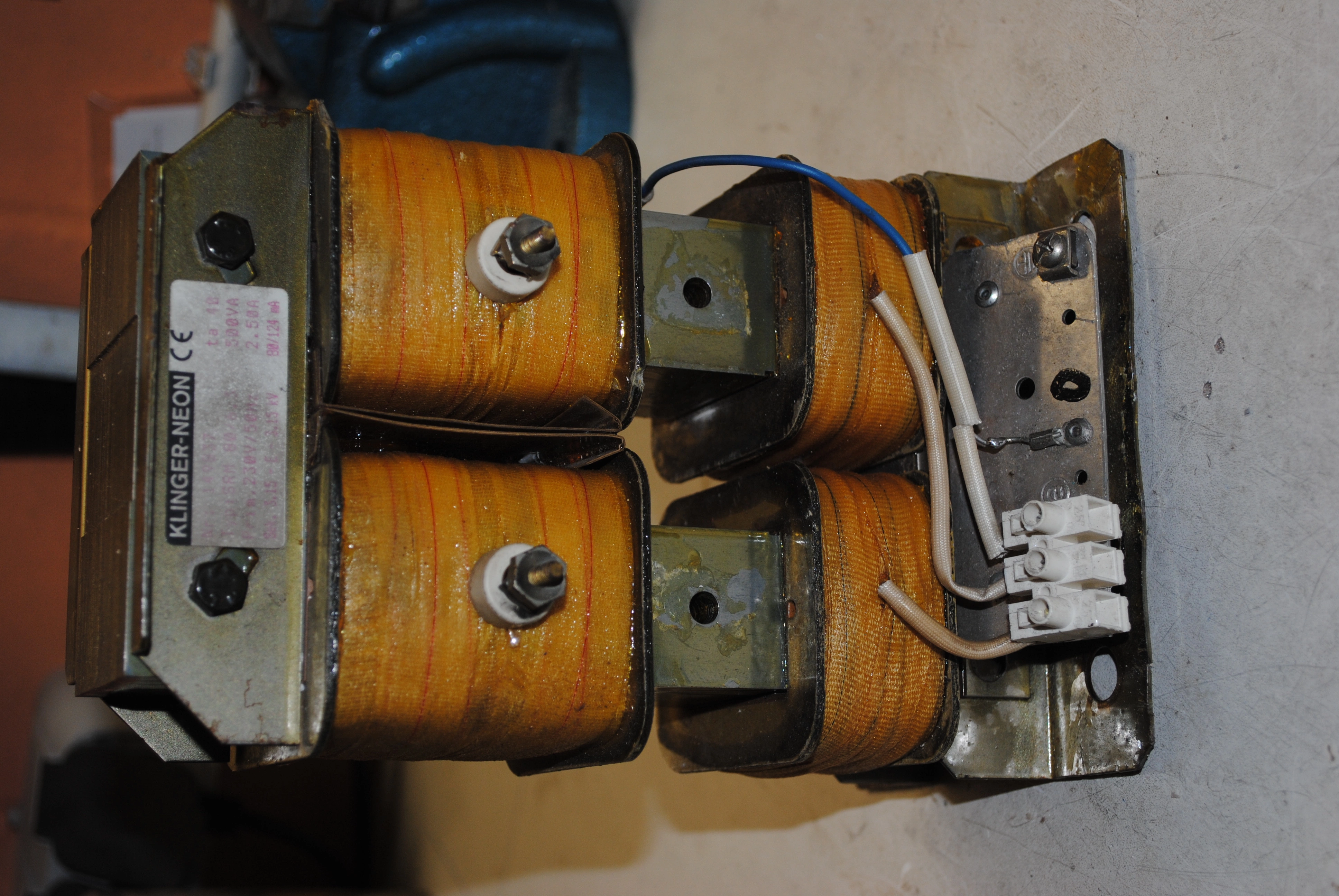
 Neon Sign Transformer (NST)
I have used Neon Sign Transformers for all of my larger tesla coil systems. I always chose the older style transformers because they feature an adjustable core to adjust the output current.
By removing this core entirely, the transformer's output current can inscreased substantially. With the core removed, the transformer can no longer run continuously without overheating.
In practise this is no real issue, since a tesla coil will generally not run for much longer than a minute. The transformer of my large coil outputs 6.3kV at roughly 280mA.
Safety gap
 Safety spark gap
 My first Tesla coil
 "High school project" coil
 1.5kW Tesla coil