Track Drive Robot
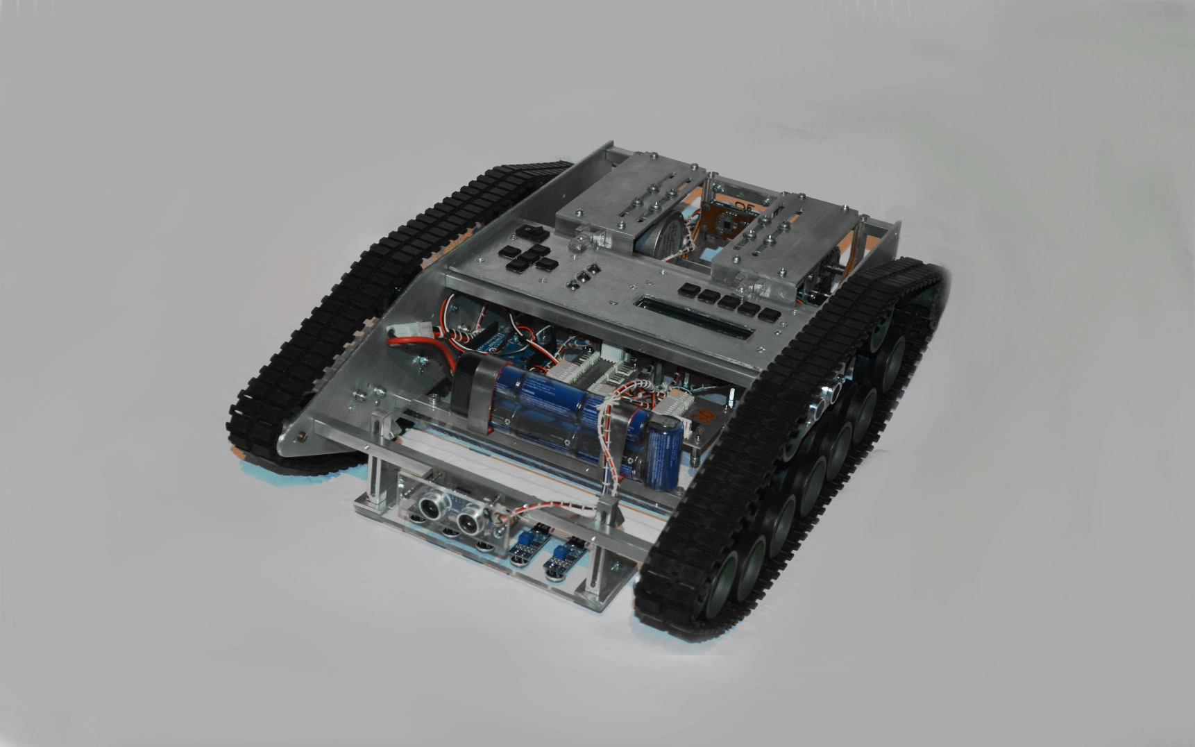
I constructed this track-drive robot together with fellow students for a university project. The goal of the project was to apply programming techniques to a mechanical engineering problem. The project assignment merely required the construction of a very simple autonomous robot, but since practical assignments are unfortunately quite rare, we decided to invest some extra time and design something nice. The robot can autonomously perform standard tasks like obstacle avoidance, parallel parking or labyrinth navigation. It also features an advanced line following logic and automatic calibration routines.
 Track driven robot
Chassis & Drive System
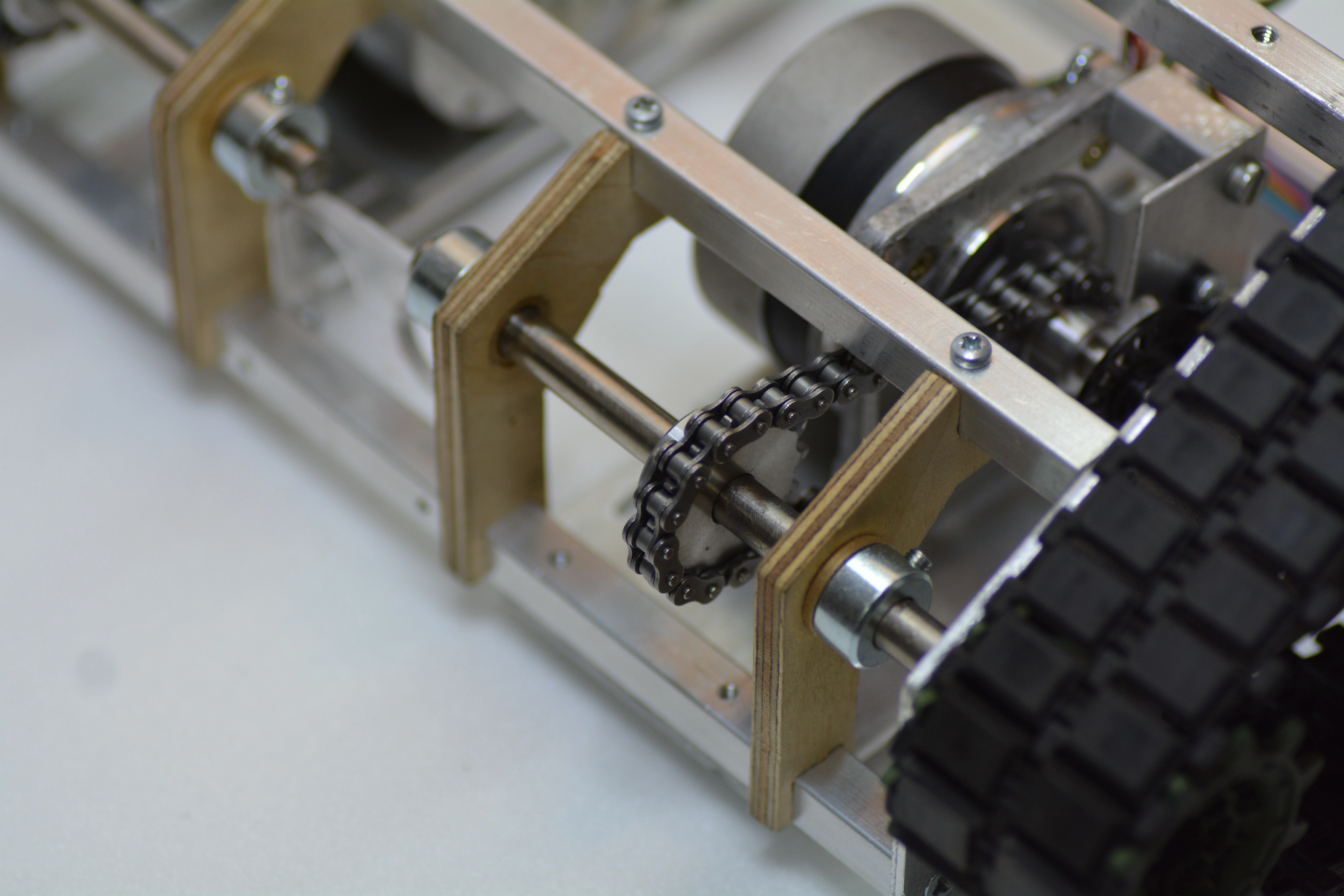
The robot is - as the name might suggest - propelled using a track drive system. The tracks and rollers were sourced from a tank modeling supply. Each track is connected to a stepper motor through a chain drive transmission. A photo interrupter was placed on each stepper motor shaft to monitor motor movement and detect stalls. The drive shafts were fabricated from 8mm ground stainless steel rod. Bronze bushings were used for mounting the shafts.
The main chassis is constructed from two pieces of aluminium sheet metal that are connected with 10mm extruded aluminium profiles.
 Stepper motor robot drive
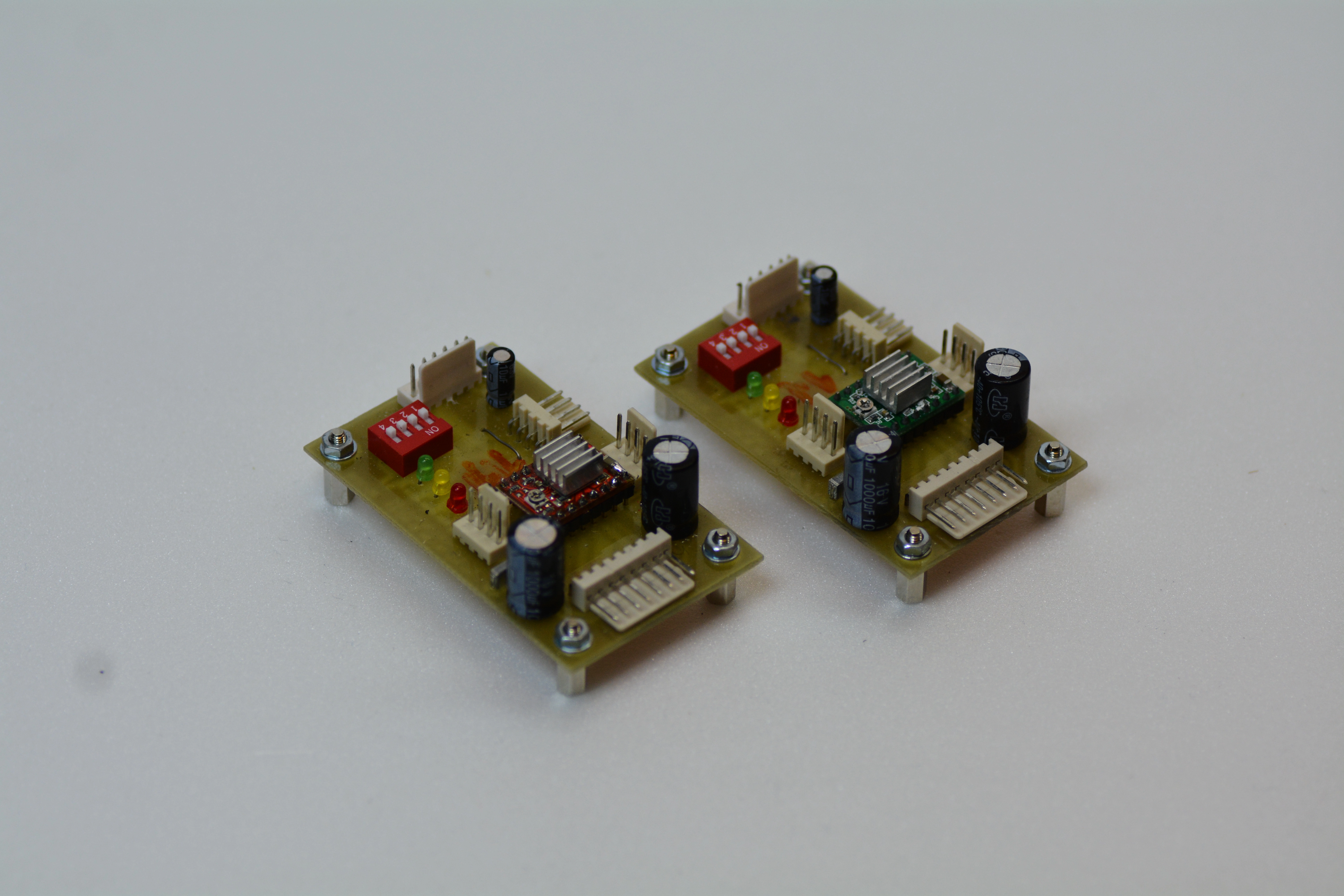
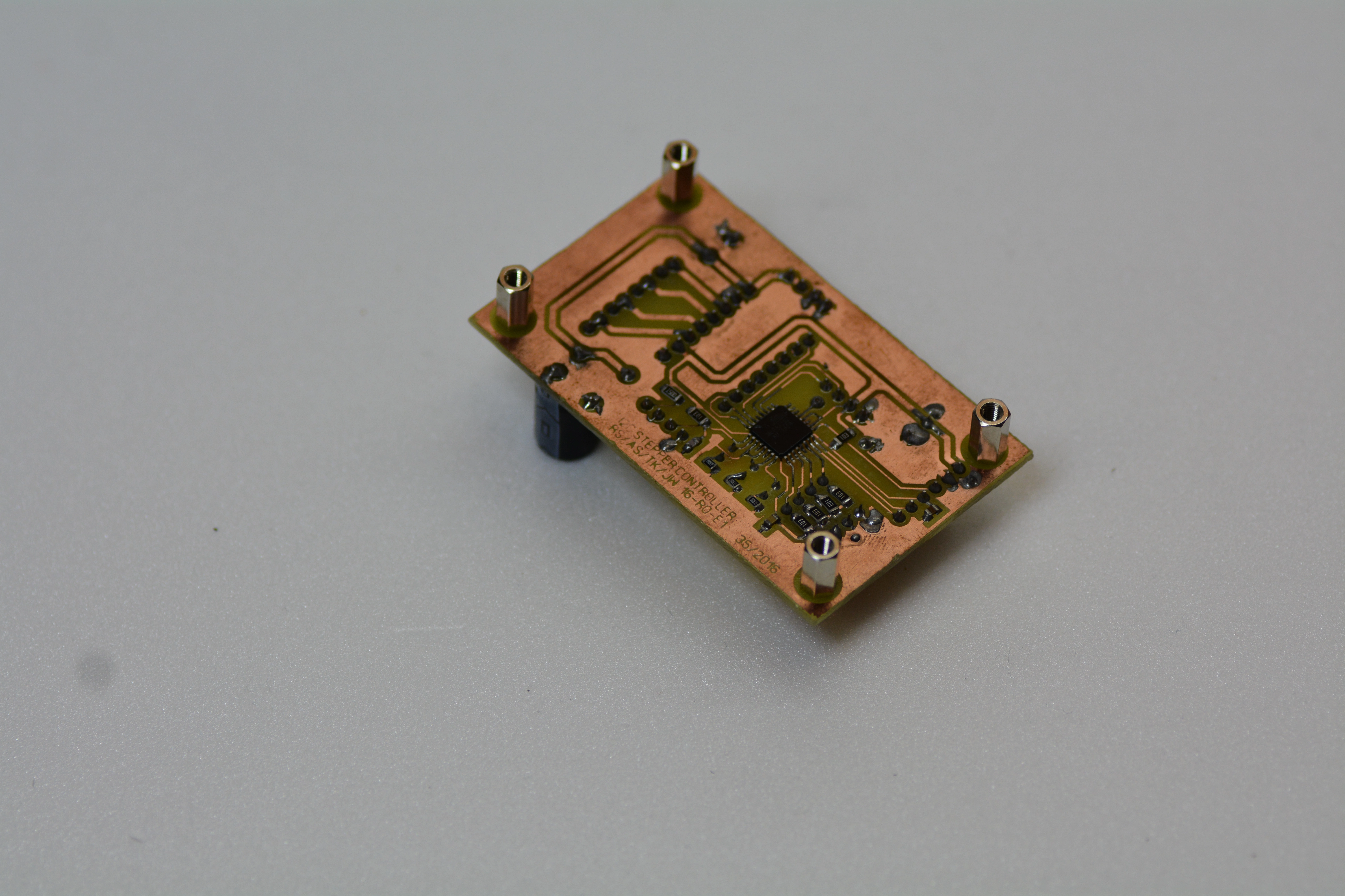
A motor driver board was designed for controlling the motors over the system bus. The control board handles various motor functions including velocity ramping and track braking. Stalls are automatically detected using the previously mentioned photo interrupted and reported to the bus controller.
 Stepper motor drivers
 Stepper motor drivers
Modular Design
The robot was designed as a modular system, with each component being connected to a centralized bus. Being a vehicle the obvious choice would have been to implement a CAN bus. Due to strict time frame we decided to reduce complexity by using a low baud rate I2C bus. Each module was consequently equipped with an I2C interface. Since this is an educational project, the bus controller was implemented on an arduino uno board, so it would be very easy to program.
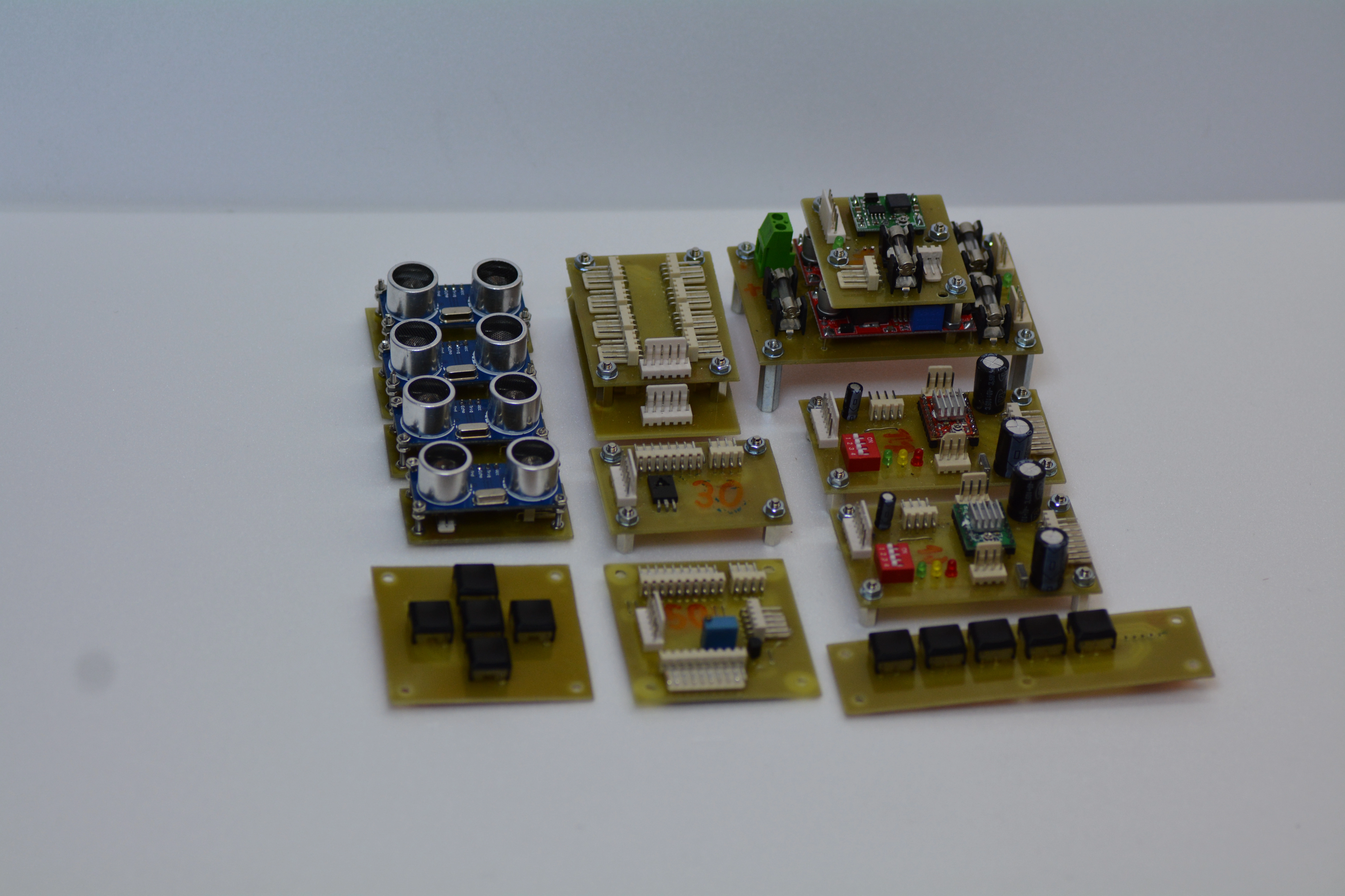 Robot modules
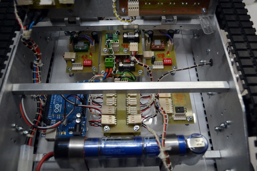 Robot electronics
Sensors
An ultrasonic distance sensor was mounted on each side of the robot. Each sensor was equipped with an adapter board for interfacing to the bus and pre-processing sensor values. A line-tracking array consisting out of five infrared reflectance sensors was mounted on the robot. The sensors interface to a separate control board the provides analog to digital conversion and connects to the system bus.
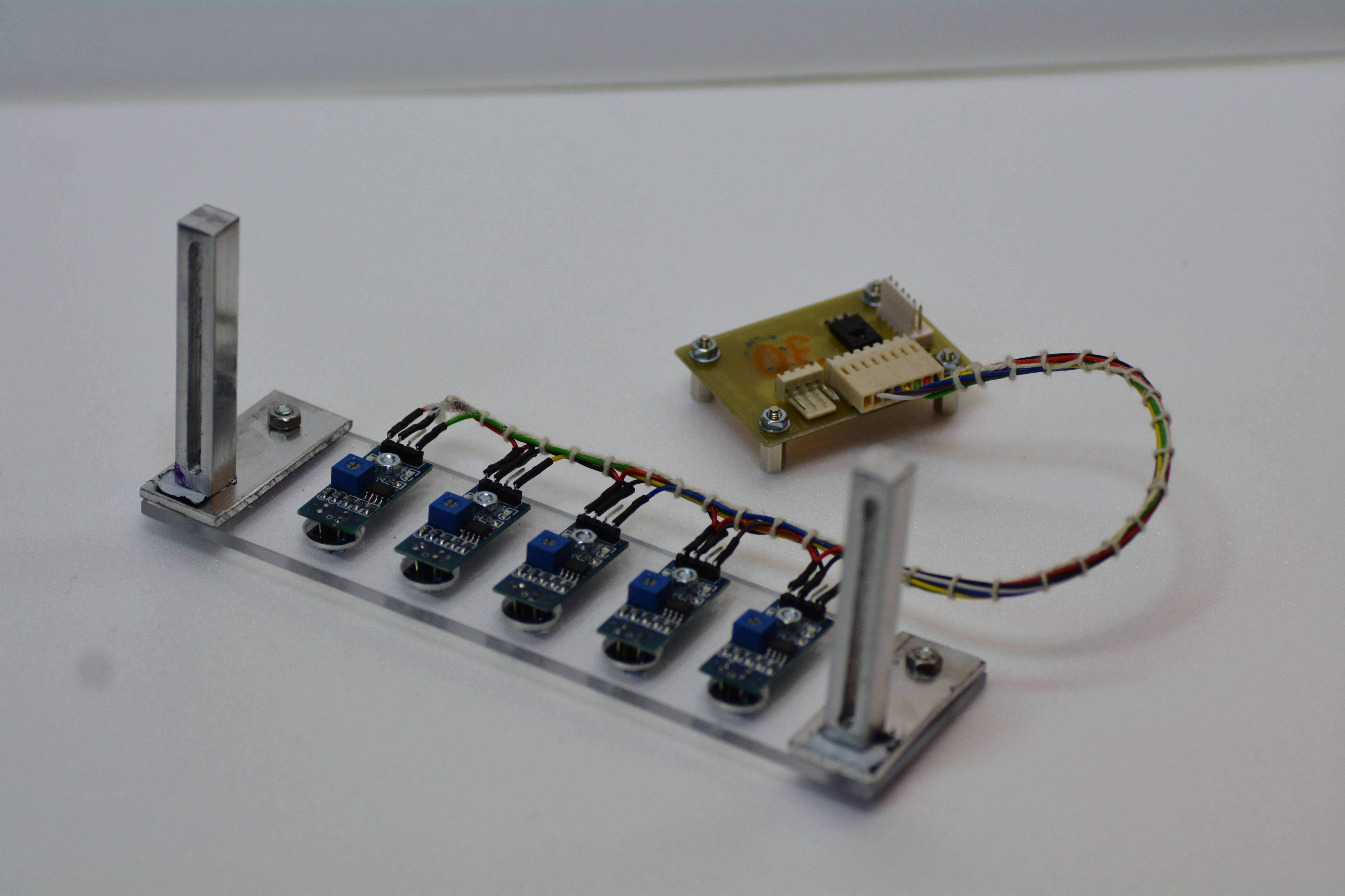 Line sensor array
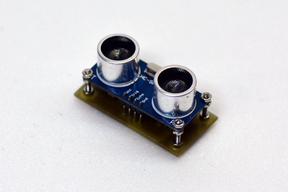 Distance sensor
Controls
A basic control panel was designed to allow user interaction. The panel features an two line LCD-Panel and a few buttons. The robot is also pre-equipped for WiFi connectivity, although this funcionality was not fully implemented.
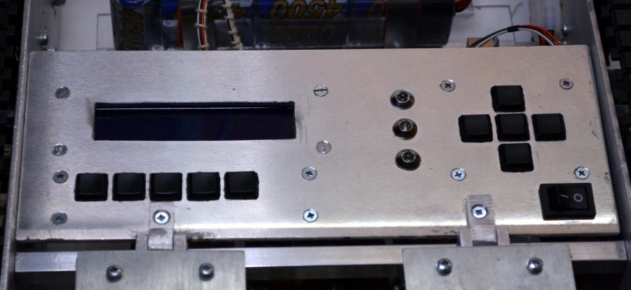 Control board
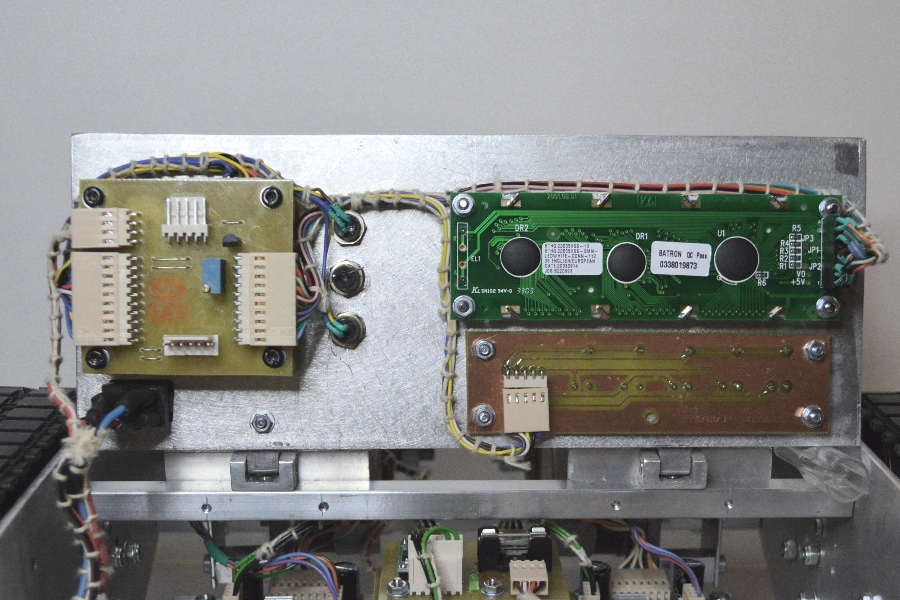 Control board wiring